When we configure PIM on our routers, we will establish PIM neighbor adjacencies, and the PIM hello messages are also used to elect a designated router for each multi-access network. The DR is the router that will forward the PIM join message from the receiver to the RP (rendezvous point).
Since the DR is used to forward PIM join messages to the RP, it doesn’t do much good for multicast dense mode where we don’t have an RP. The only exception is when you use IGMPv1…in that case, the PIM DR will work as the IGMP query router because IGMPv1 doesn’t have a query router election.
Let’s take a look at the following topology to see how the DR works:
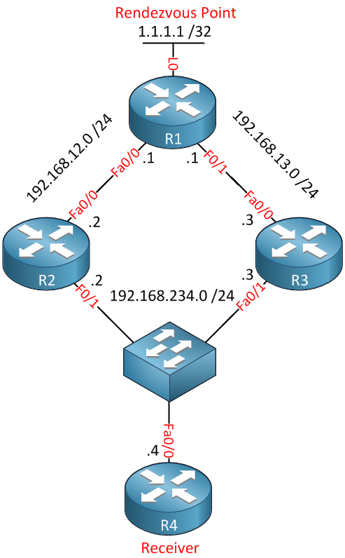
Above, we see a small network with 4 routers. R1 is our RP, and R4 is the receiver. As you can see, R2, R3, and R4 are connected to the same multi-access network (switch). When R4 sends an IGMP join message, both R2 and R3 would receive it and forward it to R1. This would mean that we have 2 multicast streams which results in duplicate packets and wasted bandwidth.
To avoid this problem, we will elect the DR. R2 or R3 will become the designated router, and only one of them will forward the PIM join message to our RP.
Let’s configure this small network and take a close look at how the DR works:
R1(config)#ip multicast-routing
R1(config)#ip pim rp-address 1.1.1.1

R1(config)#interface loopback 0
R1(config-if)#ip pim sparse-mode

R1(config)#interface fastEthernet 0/0
R1(config-if)#ip pim sparse-mode

R1(config)#interface fastEthernet 0/1
R1(config-if)#ip pim sparse-mode
We will use the loopback interface on R1 to advertise as the RP.
R2(config)#ip multicast-routing
R2(config)#ip pim rp-address 1.1.1.1

R2(config)#interface fastEthernet 0/0
R2(config-if)#ip pim sparse-mode

R2(config)#interface fastEthernet 0/1
R2(config-if)#ip pim sparse-modeR3(config)#ip multicast-routing
R3(config)#ip pim rp-address 1.1.1.1
R3(config)#interface fastEthernet 0/0
R3(config-if)#ip pim sparse-mode
R3(config)#interface fastEthernet 0/1
R3(config-if)#ip pim sparse-modeR4(config)#ip multicast-routing
R2 and R3 are configured for sparse mode and a static RP, R4 is only a receiver, so we don’t need PIM.
R2#show ip pim neighbor
PIM Neighbor Table
Mode: B - Bidir Capable, DR - Designated Router, N - Default DR Priority,
      S - State Refresh Capable
Neighbor          Interface                Uptime/Expires    Ver   DR
Address                                                            Prio/Mode
192.168.12.1      FastEthernet0/0          01:24:25/00:01:28 v2    1 / S
192.168.234.3     FastEthernet0/1          01:24:29/00:01:26 v2    1 / DR S
R3 has been elected as the Designated router on this segment. Why? because by default, the highest IP address will determine who becomes the PIM DR. Now let’s enable a debug to see what the designated router really does for us:
R2#debug ip pim
PIM debugging is onR3#debug ip pim
PIM debugging is onWe will use debug ip pim on R2 and R3. Now we will join a multicast group on R4:
R4(config)#interface fastEthernet 0/0
R4(config-if)#ip igmp join-group 239.1.1.1
R4 will join multicast group 239.1.1.1. Now let’s see what R2 and R3 think of this:
R2#
Check RP 1.1.1.1 into the (*, 239.1.1.1) entry
Above, you see that R2 doesn’t do much with it, it does add 1.1.1.1 as the RP for multicast group 239.1.1.1. You can see it here:
R2#show ip mroute 239.1.1.1
IP Multicast Routing Table
Flags: D - Dense, S - Sparse, B - Bidir Group, s - SSM Group, C - Connected,
       L - Local, P - Pruned, R - RP-bit set, F - Register flag,
       T - SPT-bit set, J - Join SPT, M - MSDP created entry,
       X - Proxy Join Timer Running, A - Candidate for MSDP Advertisement,
       U - URD, I - Received Source Specific Host Report,
       Z - Multicast Tunnel, z - MDT-data group sender,
       Y - Joined MDT-data group, y - Sending to MDT-data group
Outgoing interface flags: H - Hardware switched, A - Assert winner
 Timers: Uptime/Expires
 Interface state: Interface, Next-Hop or VCD, State/Mode

(*, 239.1.1.1), 00:11:38/00:02:19, RP 1.1.1.1, flags: SP
  Incoming interface: FastEthernet0/0, RPF nbr 192.168.12.1
  Outgoing interface list: Null
Above, you see that it created an entry for the 239.1.1.1 group address with 1.1.1.1 as the RP. Now let’s take a look at R3:
Thanks Rene, a very useful tutorial on ip pim, espescially on Designated Router, how a receiver joins a group and how the Rendezvous Point is mapped to the group. Fundamentals of ip pim sparse mode which i am working with. Thank you.
You are welcome Kevin, glad to hear you like it.
Thank You..
Very nice explanation - appreciated.
Too good. it is very crisp and clear. Answered to the point.
Too good. Keep posting similar posts for other multicast technologies as well.
Thanks,