In this lesson you will learn about VRFs (Virtual Routing and Forwarding). By default a router uses a single global routing table that contains all the directly connected networks and prefixes that it learned through static or dynamic routing protocols.
VRFs are like VLANs for routers, instead of using a single global routing table we can use multiple virtual routing tables. Each interface of the router is assigned to a different VRF.
VRFs are commonly used for MPLS deployments, when we use VRFs without MPLS then we call it VRF lite. That’s what we will focus on in this lesson. Let’s take a look at an example topology:
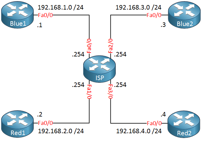 In the topology above we have one ISP router and two customers called “Red” and “Blue”. Each customer has two sites and those are connected to the ISP router. The ISP router has only one global routing table so if we connect everything like the topology above, this is what the routing table will look like:
ISP#show ip route connected
C    192.168.4.0/24 is directly connected, FastEthernet3/0
C    192.168.1.0/24 is directly connected, FastEthernet0/0
C    192.168.2.0/24 is directly connected, FastEthernet1/0
C    192.168.3.0/24 is directly connected, FastEthernet2/0
The ISP router has a single global routing table that has all 4 directly connected networks. Let’s use VRFs to change this, I want to create a seperate routing table for customer “Blue” and “Red”. First we have to create these VRFs:
ISP(config)#ip vrf Red
ISP(config-vrf)#exit
ISP(config)#ip vrf Blue
ISP(config-vrf)#exit
Globally we create the VRFs, one for each customer. Our next step is to add the interfaces of the ISP router to the correct VRF. Here’s how:
ISP(config)#interface FastEthernet 0/0
ISP(config-if)#ip vrf forwarding Blue
% Interface FastEthernet0/0 IP address 192.168.1.254 removed due to enabling VRF Blue
ISP(config-if)#ip address 192.168.1.254 255.255.255.0
On the interface level we use the ip vrf forwarding command to assign the interface to the correct VRF. Once you do this , you’ll have to add the IP address again. Let’s configure the remaining interfaces:
ISP(config)#interface FastEthernet 1/0
ISP(config-if)#ip vrf forwarding Red
ISP(config-if)#ip address 192.168.2.254 255.255.255.0

ISP(config)#interface FastEthernet 2/0
ISP(config-if)#ip vrf forwarding Blue
ISP(config-if)#ip address 192.168.3.254 255.255.255.0

ISP(config)#interface FastEthernet 3/0
ISP(config-if)#ip vrf forwarding Red
ISP(config-if)#ip address 192.168.4.254 255.255.255.0
All interfaces are now configured. There’s a useful command you can use to see all the VRFs and their interfaces:
ISP#show ip vrf
  Name                             Default RD          Interfaces
  Blue                                                 Fa0/0
                                                       Fa2/0
  Red                                                  Fa1/0
                                                       Fa3/0
Our VRFs are configured, let’s take a look at the global routing table of the ISP router:
ISP#show ip route connected
The global routing table has no entries, this is because all interfaces were added to a VRF. Let’s check the VRF routing tables:
ISP#show ip route vrf Blue connected
C    192.168.1.0/24 is directly connected, FastEthernet0/0
C 192.168.3.0/24 is directly connected, FastEthernet2/0ISP#show ip route vrf Red connected
C 192.168.4.0/24 is directly connected, FastEthernet3/0
C 192.168.2.0/24 is directly connected, FastEthernet1/0We use the show ip route command but you’ll need to specify which VRF you want to look at. As you can see, each VRF has its own routing table with the interfaces that we configured earlier.
If you want to do something on the router like sending a ping then you’ll have to specify which VRF you want to use. By default it will use the global routing table. Here’s an example how to send a ping:
ISP#ping vrf Blue 192.168.1.1

Type escape sequence to abort.
Sending 5, 100-byte ICMP Echos to 192.168.1.1, timeout is 2 seconds:
!!!!!
Success rate is 100 percent (5/5), round-trip min/avg/max = 1/2/4 ms
That’s easy enough, just don’t forget to specify the correct VRF. The same thing applies to routing (protocols). For example if you want to configure a static route you’ll have to specify the correct VRF. Take a look at the example below:
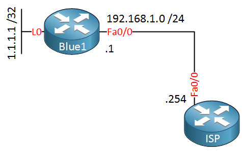
Router Blue1 has a loopback interface with IP address 1.1.1.1 /32. Let’s create a static route on the ISP router so that we can reach it:
ISP(config)#ip route vrf Blue 1.1.1.1 255.255.255.255 192.168.1.1We use the same ip route command but I specified to what VRF the static route belongs. Let’s see if this works:
ISP#ping vrf Blue 1.1.1.1

Type escape sequence to abort.
Sending 5, 100-byte ICMP Echos to 1.1.1.1, timeout is 2 seconds:
!!!!!
Success rate is 100 percent (5/5), round-trip min/avg/max = 8/24/52 ms
Easy enough, the ping works. What about routing protocols? We can use OSPF, EIGRP, BGP…no problem at all. Let’s look at an example for OSPF:
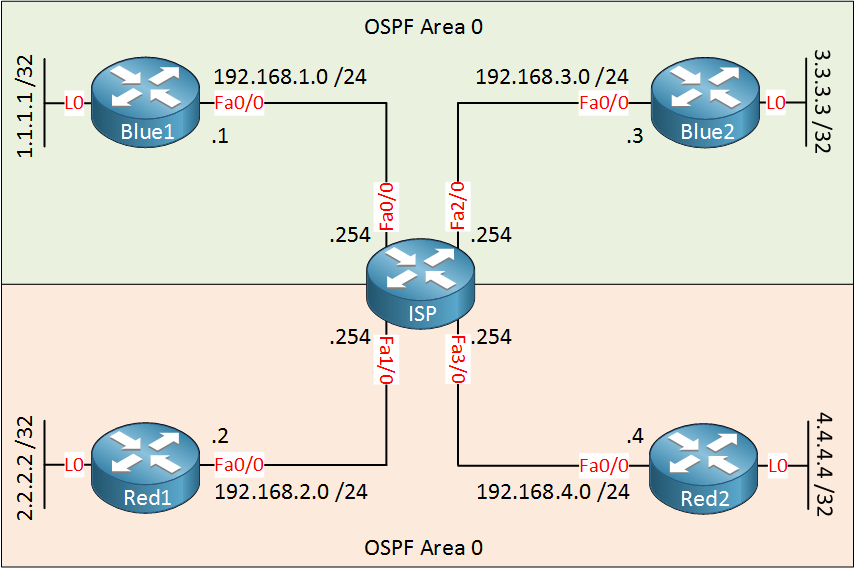
Customer “Blue” and “Red” both want to use OSPF to advertise their networks. Since we use VRFs, everything is seperated. Let’s start with the OSPF configuration for customer Blue:
Blue1(config)#router ospf 1
Blue1(config-router)#network 192.168.1.0 0.0.0.255 area 0
Blue1(config-router)#network 1.1.1.1 0.0.0.0 area 0Blue2(config)#router ospf 1
Blue2(config-router)#network 192.168.3.0 0.0.0.255 area 0
Blue2(config-router)#network 3.3.3.3 0.0.0.0 area 0The OSPF configuration for the customer routers is pretty straight-forward. On the ISP router, we’ll have to specify what VRF we want to use:
ISP(config)#router ospf 1 vrf Blue
ISP(config-router)#network 192.168.1.0 0.0.0.255 area 0
ISP(config-router)#network 192.168.3.0 0.0.0.255 area 0
We configure OSPF process 1 and specify the VRF that we want to use, that’s all there is to it. Let’s do the same for customer Red:
Red1(config)#router ospf 1
Red1(config-router)#network 192.168.2.0 0.0.0.255 area 0
Red1(config-router)#network 2.2.2.2 0.0.0.0 area 0Red2(config)#router ospf 1
Red2(config-router)#network 192.168.4.0 0.0.0.255 area 0
Red2(config-router)#network 4.4.4.4 0.0.0.0 area 0ISP(config)#router ospf 2 vrf Red
ISP(config-router)#network 192.168.2.0 0.0.0.255 area 0
ISP(config-router)#network 192.168.4.0 0.0.0.255 area 0The configuration is similar, I had to use another process ID on the ISP router since the first one is used for customer Blue. Here’s what the VRF routing tables on the ISP router look like now:
ISP#show ip route vrf Blue ospf

Routing Table: Blue

     1.0.0.0/32 is subnetted, 1 subnets
O       1.1.1.1 [110/2] via 192.168.1.1, 00:00:24, FastEthernet0/0
     3.0.0.0/32 is subnetted, 1 subnets
O 3.3.3.3 [110/2] via 192.168.3.3, 00:00:24, FastEthernet2/0ISP#show ip route vrf Red ospf
Routing Table: Red
2.0.0.0/32 is subnetted, 1 subnets
O 2.2.2.2 [110/2] via 192.168.2.2, 00:00:19, FastEthernet1/0
4.0.0.0/32 is subnetted, 1 subnets
O 4.4.4.4 [110/2] via 192.168.4.4, 00:00:19, FastEthernet3/0Two seperate routing tables with the prefixes from each VRF, this is looking good.
Configurations
Want to take a look for yourself? Here you will find the final configuration of each device.
Hi Rene,
Thank you for your efforts. I was waiting for VRF tutorial for a long time. You have explained this clearly. BTW, do you have plan to upload Inter-VRF routing with MP-BGP ?
Hi Ronie,
You are welcome, glad you like it. I’ll add inter-VRF routing with MP-BGP / MPLS for sure
Rene
René,
Congrats for share this excellent explanation!!! I’m from Brazil and I don’t have a good English, but I can understand each word, sentence that you used in this article. I never had understood about this subject, maybe because I really didn’t study it with attention and deeply. I’m a beginner Network Admin and when I saw this article in my feed I started to read it and understand it and I’m amazing how you can teach it like this way.
But I have a doubt where I can’t see in examples above. Using this topology, if tomorrow for any reason Blue and Red make a
... Continue reading in our forumHi Gabriel,
I’m glad to hear that you like it! Your question is a good one. If you want to use “shared services” between VRFs then there are two solutions:
I’ll create some examples for MP-BGP.
Rene
Rene,
Thanks your attention!!! I’ll study more about this concept.
Please, keep this excellent job!
Abraço