Lesson Contents
BGP routers must establish a neighbor adjacency before they can exchange any routing information. To establish the neighbor adjacency, we go through different stages called BGP states. It’s important to understand these states because when the neighbor adjacency fails, it will show you in what state the neighbor adjacency is. In this lesson, we’ll take a closer look at these different BGP states and I’ll show you what they look like on Cisco IOS routers.
Key Takeaways
- BGP uses six states to establish neighbor adjacencies:
- Idle
- Connect
- Active
- OpenSent
- OpenConfirm
- Established
- If BGP gets stuck in the Active state, it typically indicates a TCP connection problem.
- The Established state is the only operational state where routing information is exchanged.
- One router will be active and one passive during the connection process.
Prerequisites
Before diving into BGP neighbor states, you should have a basic understanding of BGP.
BGP States
Let’s look at the BGP states one-by-one.
Idle
This is the first state where BGP waits for a “start event”. The start event occurs when someone configures a new BGP neighbor or when we reset an established BGP peering. After the start event, BGP will initialize some resources, resets a ConnectRetry timer and initiates a TCP connection to the remote BGP neighbor. It will also start listening for a connection in case the remote BGP neighbor tries to establish a connection. When successful, BGP moves to the Connect state. When it fails, it will remain in the Idle state.
Connect
BGP is waiting for the TCP three-way handshake to complete. When it is successful, it will continue to the OpenSent state. In case it fails, we continue to the Active state. If the ConnectRetry timer expires then we will remain in this state. The ConnectRetry timer will be reset and BGP will try a new TCP three-way handshake. If anything else happens (for example resetting BGP) then we move back to the Idle state.
Active
BGP will try another TCP three-way handshake to establish a connection with the remote BGP neighbor. If it is successful, it will move to the OpenSent state. If the ConnectRetry timer expires then we move back to the Connect state. BGP will also keep listening for incoming connections in case the remote BGP neighbor tries to establish a connection. Other events can cause the router to go back to the Idle state (resetting BGP for example).
OpenSent
In this state BGP will be waiting for an Open message from the remote BGP neighbor. The Open message will be checked for errors, if something is wrong (incorrect version numbers, wrong AS number, etc.) then BGP will respond with a Notification message and jumps back to the Idle state. This is also the moment where BGP decides whether we use EBGP or IBGP (since we check the AS number). If everything is OK then BGP starts sending keepalive messages and resets its keepalive timer. At this moment, the hold time is negotiated (lowest value is picked) between the two BGP routers. In case the TCP session fails, BGP will jump back to the Active state. When any other errors occur (expiration of hold timer), BGP will send a notification message with the error code and jumps back to the Idle state. In case someone resets the BGP process, we also jump back to the Idle state.
OpenConfirm
BGP waits for a keepalive message from the remote BGP neighbor. When we receive the keepalive, we can move to the established state and the neighbor adjacency will be completed. When this occurs, it will reset the hold timer. If we receive a notification message from the remote BGP neighbor then we fall back to the Idle state. BGP will keep sending keepalive messages.
Established
The BGP neighbor adjacency is complete and the BGP routers will send update packets to exchange routing information. Every time we receive a keepalive or update message, the hold timer will be resetted. In case we receive a notification message we will jump back to the Idle state.
Finite State Machine (FSM)
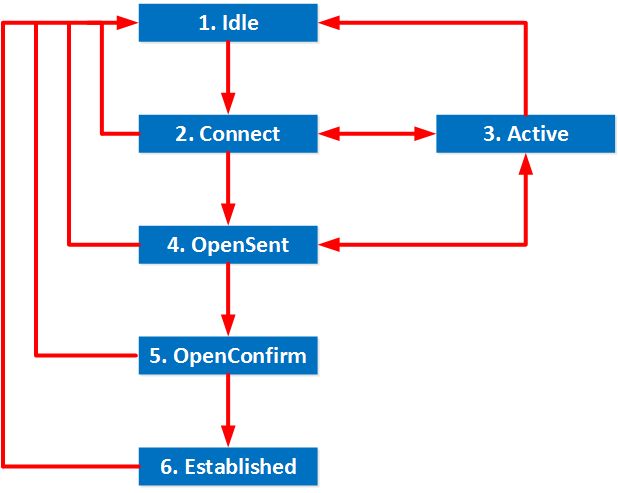
This whole process of becoming BGP neighbors can be visualized, this might be a bit easier then just reading about it. The official name of a “diagram” that shows the different states and we can move from one state to another is called a FSM (Finite State Machine). For BGP, it looks like this:

Configuration
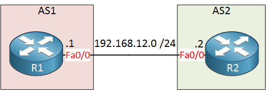
Now you know about the different states, let’s take a look at some Cisco BGP routers to see what it actually looks like on two routers. I’ll use the following topology for this:

Just two routers in two different autonomous systems. Before I configure BGP, let’s enable a debug:


This information on how BGP neighbors establish adjacency is articulate and useful. Thank You!
Joey
Hi Rene
Thank you for great article. I had a question though.
Why didn’t R1 enter connect state and instead shifted to Active straight from idle? On the other hand i see R2 did enter connect state?
thanks
Kandhla
Hi Kandhla,
Good question, I’m not sure why it doesn’t show up initially…
Rene
Hei Rene,
Thanks for the lesson, in my working experience, i am stuck in a situation for 2 sites. i have the ebgp peering up, but i am receiving 0 prefix from my isp. The isp said when they show ip bgp nei adverticed route that are hundreds of routes advertised, they can receive our route. Any good debug command to troule should this? We have plain bgp config, the same config (different peering ip though) is working with other sites.
One interesting thing is that when i ping the isp with mtu 1500 it does not work, but it works with 1496. After reading cisco doc
... Continue reading in our forumHi Jie,
It’s possible that the MTU is causing your issue. Your ISP might be sending BGP updates of 1500 bytes which are dropped on your end. Here’s the default TCP segment size that is used for BGP:
The segment size is 1460 bytes, add a TCP header (20 bytes) and IP header (20 bytes) and you have a 1500 byte packet. In other words, you should be able to send/receive up to 1500 bytes which is not possible at the moment.
There’
... Continue reading in our forum