Lesson Contents
In a network where you have a layer two switch connected to multicast routers, all multicast traffic is flooded to all multicast router ports, even if there are no multicast receivers behind a router.
When you enable PIM snooping, the switch will learn which multicast router ports should receive traffic by looking at PIM hello, join, prune, and designated forward election messages.
Let’s look at some examples:
 .
.
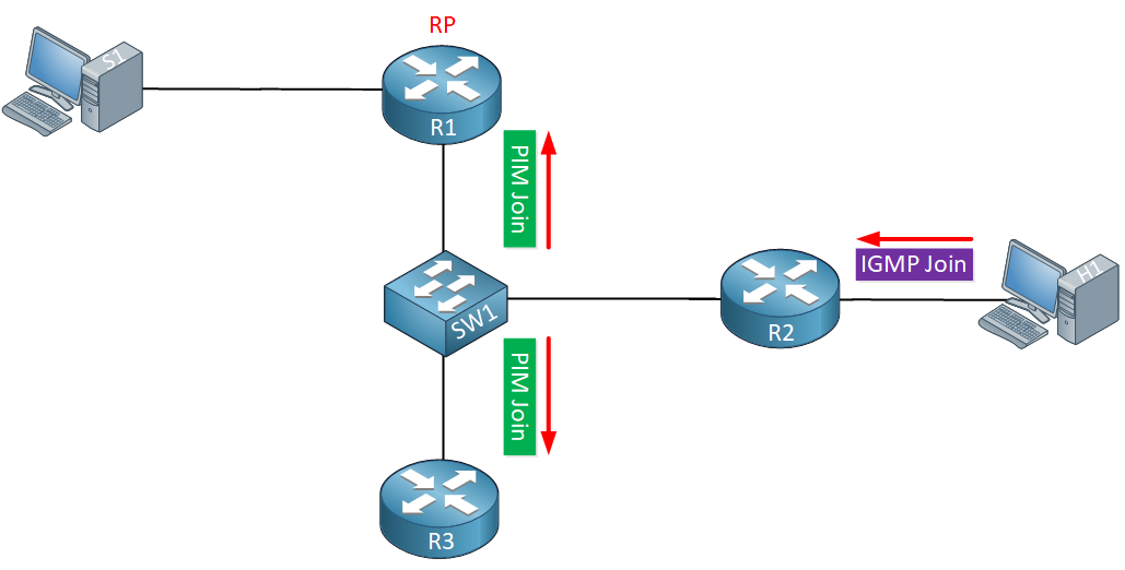
Above we have a small network where SW1 is connected to three multicast routers, R1, R2, and R3. R1 is our RP. Behind R2, we have a receiver that is interested in a multicast group so it sends an IGMP join.
This IGMP join should only be forwarded to the RP (R1) but in reality, it also ends up at R3 since our switch floods all multicast traffic.
What about data traffic?

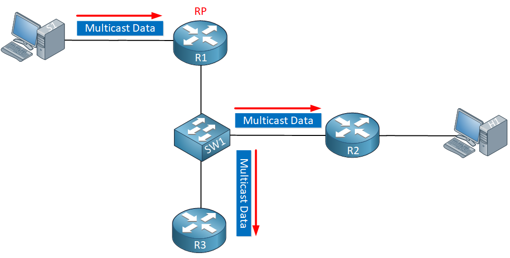
Once our source starts sending multicast traffic, the switch will flood it everywhere so it ends up at R2 (which needs it) but also at R3 that doesn’t have any receivers.
Once we enable PIM snooping, our switch will no longer flood unnecessary PIM join/prune messages nor will it forward multicast traffic to routers that don’t need it.
Some things to keep in mind about PIM snooping:
- PIM dense mode traffic is dropped once you enable PIM snooping.
- Traffic to Auto RP groups (224.0.1.39 and 224.0.1.40) are always flooded.
- PIM snooping and IGMP snooping can be enabled at the same time.
- Multicast router port and router information is timed out based on the hold time that the switch sees in PIM hello, join, and prune packets.
Configuration
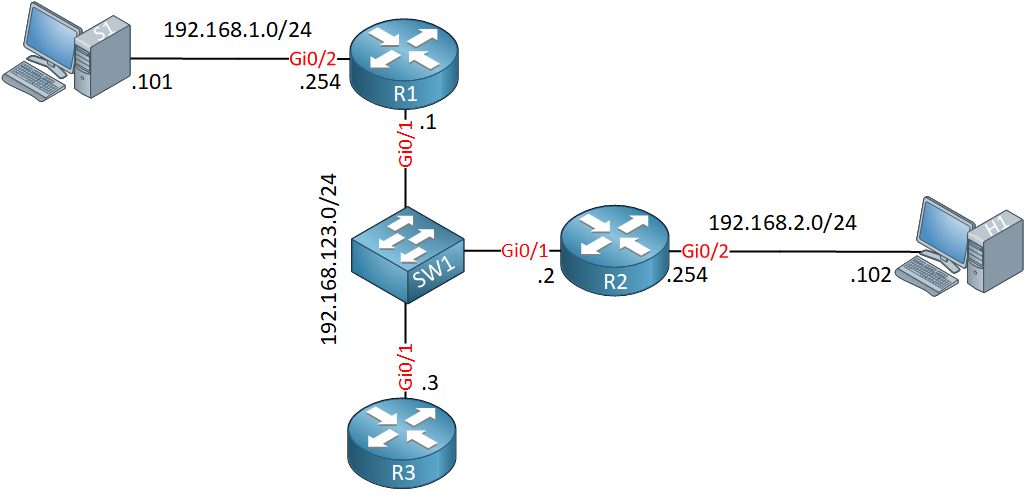
Let’s take a look at this in action. I’ll use the topology I showed you before, but added some interface numbers:

R1, R2, and R3 are multicast routers running PIM sparse mode. R1 is the RP in this network. S1 is our source, H1 is a receiver.
Configurations
Want to take a look for yourself? Here you will find the startup configuration of each device.
H1
hostname H1
!
no ip routing
!
no ip cef
!
interface GigabitEthernet0/0
 ip address 10.255.0.94 255.255.0.0
!
interface GigabitEthernet0/1
 ip address 192.168.2.102 255.255.255.0
 ip igmp join-group 239.1.1.1
!
ip default-gateway 192.168.2.254
!
end
R1
hostname R1
!
ip multicast-routing
ip cef
!
interface Loopback0
 ip address 1.1.1.1 255.255.255.255
 ip pim sparse-mode
!
interface GigabitEthernet0/1
 ip address 192.168.123.1 255.255.255.0
 ip pim sparse-mode
!
interface GigabitEthernet0/2
 ip address 192.168.1.254 255.255.255.0
 ip pim sparse-mode
!
router ospf 1
 network 1.1.1.1 0.0.0.0 area 0
 network 192.168.1.0 0.0.0.255 area 0
 network 192.168.123.0 0.0.0.255 area 0
!
ip pim rp-address 1.1.1.1
!
end
R2
hostname R2
!
ip multicast-routing
ip cef
!
interface GigabitEthernet0/1
 ip address 192.168.123.2 255.255.255.0
 ip pim sparse-mode
!
interface GigabitEthernet0/2
 ip address 192.168.2.254 255.255.255.0
 ip pim sparse-mode
!
router ospf 1
 router-id 2.2.2.2
 network 192.168.2.0 0.0.0.255 area 0
 network 192.168.123.0 0.0.0.255 area 0
!
ip pim rp-address 1.1.1.1
!
end
R3
hostname R3
!
ip multicast-routing
ip cef
!
interface GigabitEthernet0/1
 ip address 192.168.123.3 255.255.255.0
 ip access-group MULTICAST_TRAFFIC in
 ip pim sparse-mode
!
router ospf 1
 router-id 3.3.3.3
 network 192.168.123.0 0.0.0.255 area 0
!
ip pim rp-address 1.1.1.1
!
ip access-list extended MULTICAST_TRAFFIC
 permit ip any host 239.1.1.1
 permit ip any any
!
end
S1
hostname S1
!
no ip routing
!
no ip cef
!
interface GigabitEthernet0/1
 ip address 192.168.1.101 255.255.255.0
!
ip default-gateway 192.168.1.254
!
end
PIM Snooping Disabled
PIM snooping is disabled by default. Let’s enable PIM debugging on all routers so we can see what happens behind the scenes:
R1#debug ip pim
PIM debugging is on
Let’s configure H1 to join a multicast group:
H1(config)#interface GigabitEthernet 0/1
H1(config-if)#ip igmp join-group 239.1.1.1
This will trigger some PIM join messages. We can see them here:


Great content so far!
Please update the topology pic, there the IP adress in 192.168.123.0-network for R2 and R3 must be changed.
Is pim snooping ever used as it doesn’t seem to be well covered from Cisco’s documentation, too.
Best regards
Alex
Hello Alexander
Looking at the topology pic, I’m not sure where the error is. The 192.168.123.0/24 network is shared between the three routers on interface Ge0/1 with IP addresses of .1, .2 and .3. Please elaborate on what should be corrected.
As for your other questions:
Actually, R1 is the DR as is indicated in the PIM debug messages on both R1 and R2. Although you are correct that the higher IP should be chosen as
... Continue reading in our forumHi. Thanks for your answers, didn’t see the hard-coded RP in the first moment.
Explanaition for PIM Snooping and DR traffic is sufficient.
Regarding the topology pic, the IP adresses for R2 and for R3 are wrong/ should be changed.
R2 has configured 192.168.123. 2 and topology pic shows 192.168.123. 3
R3 has configured 192.168.123. 3 and topology pic shows 192.168.123. 2
Best regards
Alex
Thanks Alex, just fixed it.
dears
... Continue reading in our forumfrom cisco document:
By default, routers that have PIM snooping enabled will flood multicast traffic to the designated router
(DR). This method of operation can send unnecessary multicast packets to the designated router. The
network must carry the unnecessary traffic, and the designated router must process and drop the
unnecessary traffic.
To reduce the traffic sent over the network to the designated router, disable designated-router flooding.
With designated-router flooding disabled, PIM snooping only passes to the designated-router traffic that
is in m