Lesson Contents
VRF Lite allows us to use multiple routing tables on a router, creating a separation similar to VLANs on switches. Each interface on the router can be assigned to a different VRF. However, what if you have some shared services or routes that should be shared between multiple VRFs?
It is possible to “leak” routes from one VRF into another. There are two options to achieve this:
- Static Routes
- MP-BGP
In this lesson, I’ll show you how to configure both options.
Configuration
This is the topology I will use:
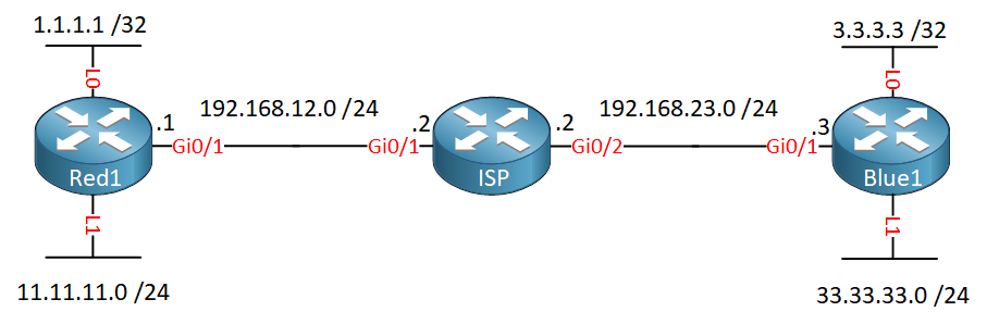
We have an ISP router that is connected to two customers. For each customer, we use a different VRF:
- VRF “RED” for Red1
- VRF “BLUE” for Blue1
Configurations
Want to take a look for yourself? Here you will find the startup configuration of each device.
ISP
hostname ISP
!
ip vrf BLUE
!
ip vrf RED
!
ip cef
!
interface GigabitEthernet0/1
 ip vrf forwarding RED
 ip address 192.168.12.2 255.255.255.0
!
interface GigabitEthernet0/2
 ip vrf forwarding BLUE
 ip address 192.168.23.2 255.255.255.0
!
end
Red1
hostname Red1
!
ip cef
!
interface Loopback0
 ip address 1.1.1.1 255.255.255.255
!
interface Loopback1
 ip address 11.11.11.11 255.255.255.255
!
interface GigabitEthernet0/1
 ip address 192.168.12.1 255.255.255.0
!
end
Blue1
hostname Blue1
!
ip cef
!
interface Loopback0
 ip address 3.3.3.3 255.255.255.255
!
interface Loopback1
 ip address 33.33.33.33 255.255.255.255
!
interface GigabitEthernet0/1
 ip address 192.168.23.3 255.255.255.0
!
end
With the configuration above, we only have connectivity within a VRF. What if we want connectivity between VRF RED and BLUE?
Static Routes
Let’s start with the static routes option. According to this Cisco document, static routes directly between VRFs are not supported. What does work, is routing traffic from a VRF to the global routing table and then to the destination VRF. One advantage of using static routes is that you can configure exactly which routes should be reachable without the hassle of configuring MP-BGP.
I’ll show you how to get connectivity between 1.1.1.1/32 in VRF RED and 3.3.3.3/32 in VRF BLUE.
Configuration
First, let’s create a default route on the Red1 and Blue1 routers so that they send all unknown traffic towards the ISP router:
Red1(config)#ip route 0.0.0.0 0.0.0.0 192.168.12.2Blue1(config)#ip route 0.0.0.0 0.0.0.0 192.168.23.2In each VRF, we add a static route for the destination in the other VRF that we want to reach. This static route is pointed to the global routing table:
ISP(config)#ip route vrf RED 3.3.3.3 255.255.255.255 192.168.23.3 global
ISP(config)#ip route vrf BLUE 1.1.1.1 255.255.255.255 192.168.12.1 global
Let me explain what you see above:
- In VRF RED, we have a static route to destination 3.3.3.3/32 that uses next hop IP address 192.168.23.3 in the global routing table.
- In VRF BLUE, we have a static route for destination 1.1.1.1/32 that uses next hop IP address 192.168.12.1 in the global routing table.
These two static routes will route traffic from the VRFs to the global routing table. These next hop addresses, however, are not in the global routing table but in the VRFs.
We need to add two static routes in the global routing table of the ISP router so that it knows how to reach the next hop addresses:
ISP(config)#ip route 192.168.12.1 255.255.255.255 GigabitEthernet 0/1
ISP(config)#ip route 192.168.23.3 255.255.255.255 GigabitEthernet 0/2
That completes our configuration.
Verification
Let’s look at the routing tables of our ISP router. Here’s the routing table of VRF RED:
ISP#show ip route vrf RED static

      3.0.0.0/32 is subnetted, 1 subnets
S        3.3.3.3 [1/0] via 192.168.23.3
Above we see the static route for 3.3.3.3/32 that points to 192.168.23.3. It doesn’t show it, but this static route points to the global routing table. Here is the route for 1.1.1.1/32 in routing table VRF BLUE:
ISP#show ip route vrf BLUE static

      1.0.0.0/32 is subnetted, 1 subnets
S        1.1.1.1 [1/0] via 192.168.12.1
Here is the global routing table:
ISP#show ip route static

      192.168.12.0/32 is subnetted, 1 subnets
S        192.168.12.1 is directly connected, GigabitEthernet0/1
      192.168.23.0/32 is subnetted, 1 subnets
S        192.168.23.3 is directly connected, GigabitEthernet0/2
Above, we see the entries for the next hop addresses in the global routing table.
The ISP router is now able to route from one VRF into the global routing table and into another VRF. Let’s try a quick ping:
Red1#ping 3.3.3.3 source 1.1.1.1
Type escape sequence to abort.
Sending 5, 100-byte ICMP Echos to 3.3.3.3, timeout is 2 seconds:
Packet sent with a source address of 1.1.1.1
!!!!!
Success rate is 100 percent (5/5), round-trip min/avg/max = 5/7/10 ms
Mission accomplished.
Configurations
Want to take a look for yourself? Here you will find the startup configuration of each device.
Blue1
hostname Blue1
!
ip cef
!
interface Loopback0
 ip address 3.3.3.3 255.255.255.255
!
interface Loopback1
 ip address 33.33.33.33 255.255.255.255
!
interface GigabitEthernet0/1
 ip address 192.168.23.3 255.255.255.0
!
ip route 0.0.0.0 0.0.0.0 192.168.23.2
!
end
ISP
hostname ISP
!
ip vrf BLUE
!
ip vrf RED
!
ip cef
!
interface GigabitEthernet0/1
 ip vrf forwarding RED
 ip address 192.168.12.2 255.255.255.0
!
interface GigabitEthernet0/2
 ip vrf forwarding BLUE
 ip address 192.168.23.2 255.255.255.0
!
ip route 192.168.12.1 255.255.255.255 GigabitEthernet0/1
ip route 192.168.23.3 255.255.255.255 GigabitEthernet0/2
ip route vrf BLUE 1.1.1.1 255.255.255.255 192.168.12.1 global
ip route vrf RED 3.3.3.3 255.255.255.255 192.168.23.3 global
!
end
Red1
hostname Red1
!
ip cef
!
interface Loopback0
 ip address 1.1.1.1 255.255.255.255
!
interface Loopback1
 ip address 11.11.11.11 255.255.255.255
!
interface GigabitEthernet0/1
 ip address 192.168.12.1 255.255.255.0
!
ip route 0.0.0.0 0.0.0.0 192.168.12.2
!
end
MP-BGP
Let’s see how we can get connectivity between the VRFs by using MP-BGP. This is pretty much the same as MPLS VPN PE CE but without MPLS. We will use MP-BGP to redistribute routes from one VRF into another.
To demonstrate this, I will redistribute static routes that I create on the ISP router into MP-BGP. Of course, you can also use a routing protocol like OSPF or EIGRP between the ISP and customer routers.
Configuration
Let’s create a default route on the customer routers that point to the ISP:
Hello Everyone,
I have a question regarding the " Static VRF routes" defined under the MP-BGP section. I believe they should look like this:
Instead of:
Am I missing something or this is just a typo?
Many thanks!
do you can ping 3.3.3.3 source 1.1.1.1 on router Red1 ? i can not do that
Hello Jose
Yes, you are correct. Rene states that:
The commands are correct in the configurations however, so yes, it should be as you suggest. I will let @ReneMolenaar know.
Thanks for catching that!
Laz
Hello Khuat Quang N
There is a typo in the commands in the lesson, so this might be why you’re not able to ping. Take a look at the previous post above. Look at the configurations of each of the routers in the lesson in order to see the correct configuration commands.
I hope this has been helpful!
Laz
You are absolutely correct, not sure how I ended up with that in the configs as the show output does show the correct output. It has been fixed.