Lesson Contents
Most students are familiar with the basics of (classic) spanning tree: how a root bridge is elected, how the switches decide what interfaces become designated, non-designated, root ports, etc.
Once the topology has converged, it doesn’t stop. Every time a switch receives a BPDU, it has to make decisions. When the topology remains the same then the switch will keep making the same decisions over and over again.
Things become interesting when we do have a change in the topology. How does spanning tree adapt to changes in the network?
In this lesson, we’ll take a look at what happens behind the scenes when the topology changes. I’ll show you the different BPDUs and the decisions that each switch will make.
Converged Topology
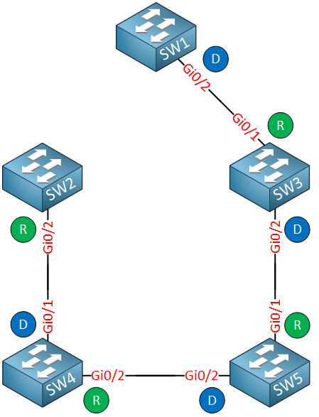
To demonstrate this, I will use the following topology:
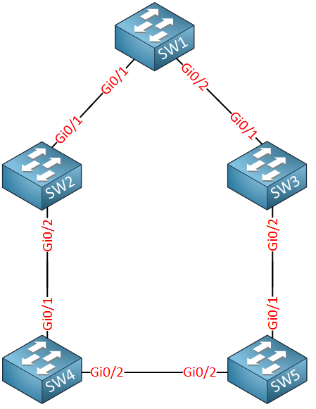
Above we have five switches. SW1 is the root bridge. Let’s check the current status of all interfaces:
SW1#show spanning-tree | begin Interface
Interface           Role Sts Cost      Prio.Nbr Type
------------------- ---- --- --------- -------- --------------------------------
Gi0/1               Desg FWD 4         128.2    P2p
Gi0/2 Desg FWD 4 128.3 P2pSW2#show spanning-tree | begin Interface
Interface Role Sts Cost Prio.Nbr Type
------------------- ---- --- --------- -------- --------------------------------
Gi0/1 Root FWD 4 128.2 P2p
Gi0/2 Desg FWD 4 128.3 P2pSW3#show spanning-tree | begin Interface
Interface Role Sts Cost Prio.Nbr Type
------------------- ---- --- --------- -------- --------------------------------
Gi0/1 Root FWD 4 128.2 P2p
Gi0/2 Desg FWD 4 128.3 P2pSW4#show spanning-tree | begin Interface
Interface Role Sts Cost Prio.Nbr Type
------------------- ---- --- --------- -------- --------------------------------
Gi0/1 Root FWD 4 128.2 P2p
Gi0/2 Desg FWD 4 128.3 P2pSW5#show spanning-tree | begin Interface
Interface Role Sts Cost Prio.Nbr Type
------------------- ---- --- --------- -------- --------------------------------
Gi0/1 Root FWD 4 128.2 P2p
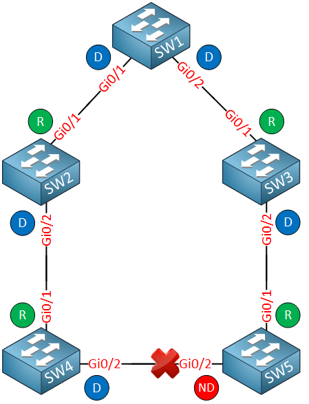
Gi0/2 Altn BLK 4 128.3 P2pLet’s create a simple diagram that has all the port statuses:
Before we start messing around with topology changes. Let’s take a look at the different BPDUs that we see on the network.
To make sense out of the different BPDUs, let me give you an overview of all MAC addresses that we will encounter:
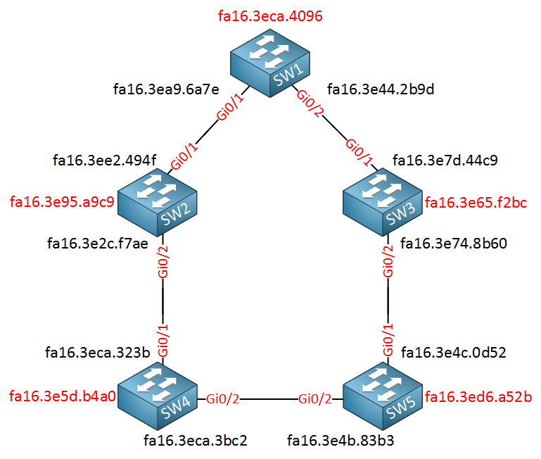
The MAC addresses in red are the MAC addresses that are used as the bridge identifiers. Spanning tree will select a MAC address of one of your (lowest) interface numbers. In my case, those were the GigabitEthernet 0/0 interfaces that I am not using in this topology. The MAC addresses in black are those of the interfaces.
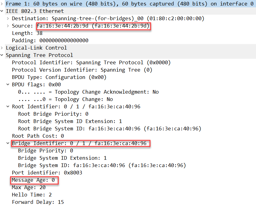
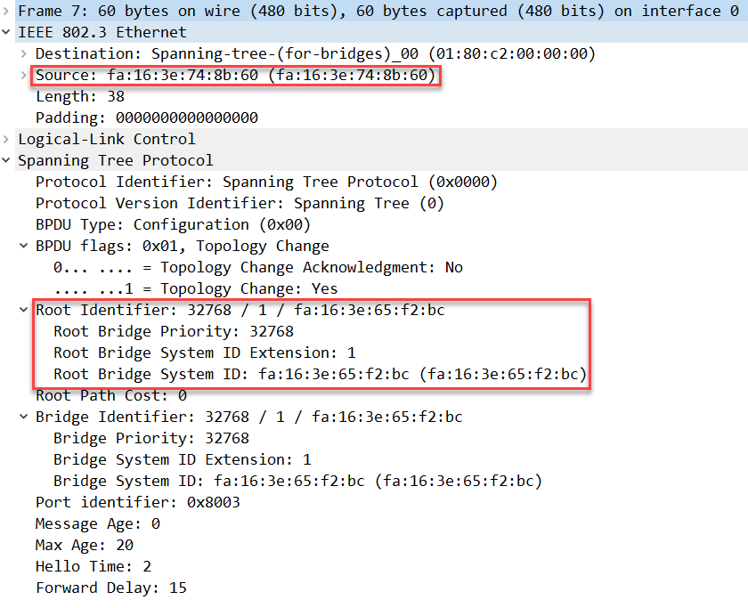
Let’s start with the BPDU that our root bridge (SW1) creates:
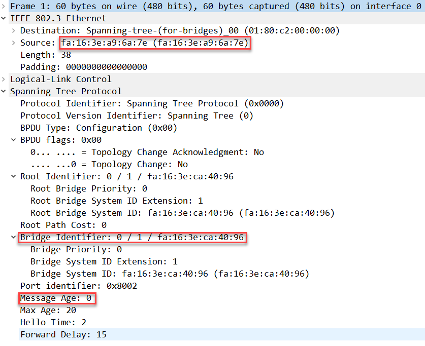
Above we see the BPDU that SW1 sends towards SW2. You can see the bridge identifier with the MAC address of SW1. I set the bridge priority to 0. Also, we can see the message age is 0. This value determines how far you are away from the root bridge. Each non-root bridge will increase this value by 1.
The message age is used to determine when a BPDU expires. You take the max age value (20) – message age (0) = 20 seconds. Switches further away from the root bridge will expire their BPDUs sooner.
Here’s the same BPDU but it’s sent towards SW3:
The contents of this BPDU are the same except for the source address.
Packet Capture: Spanning Tree Convergence SW1 SW2 BPDU
Packet Capture: Spanning Tree Convergence SW1 SW3 BPDU
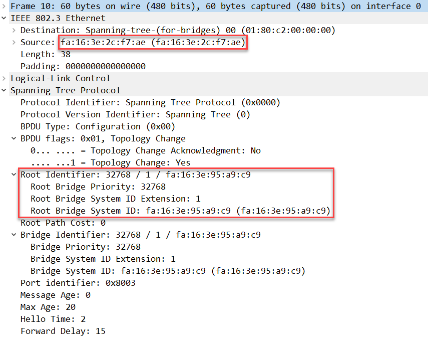
The BPDU from the root bridge is relayed by SW2 towards SW4. We can see it below:
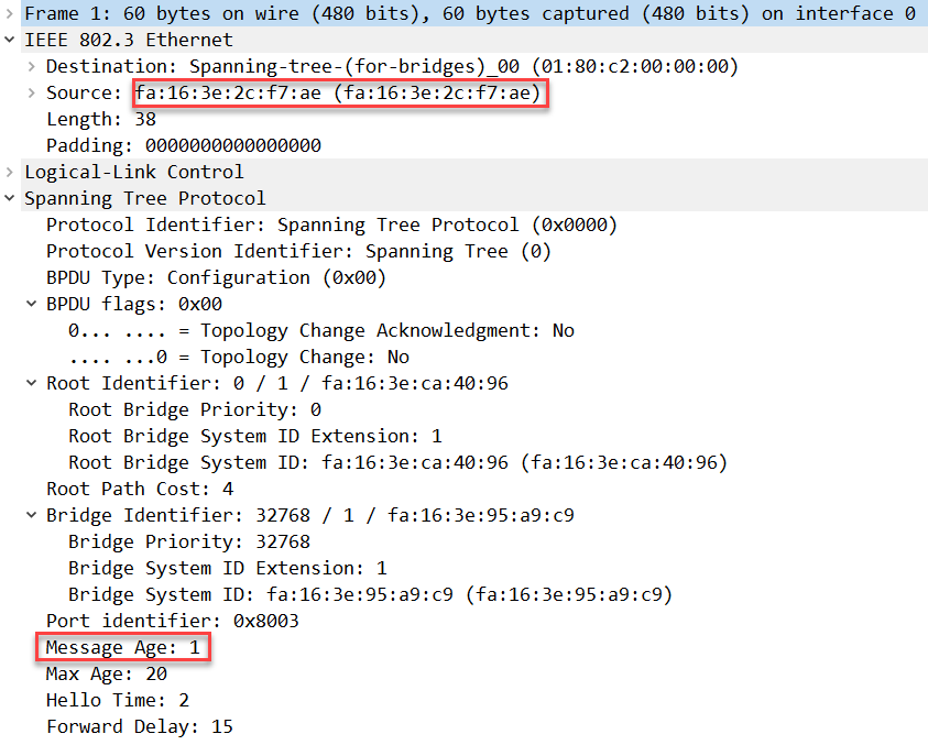
Above you can see the BPDU from SW1, the message age has been increased by 1. This means that this BPDU will expire in 20 (max age) – 1 (message age) = 19 seconds. Here’s the BPDU that SW3 relays to SW5:
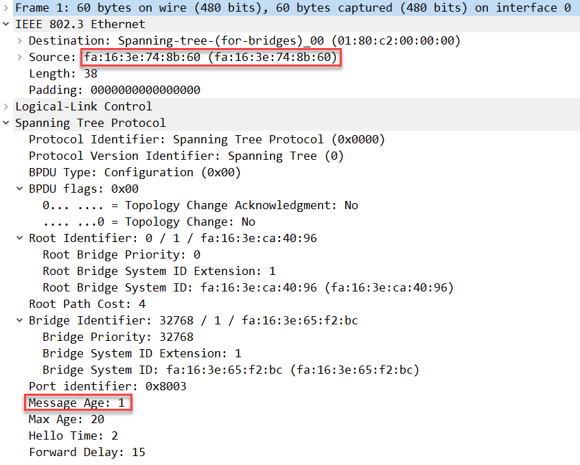
The information in the BPDU is similar.
Packet Capture: Spanning Tree Convergence SW2 SW4 BPDU
Packet Capture: Spanning Tree Convergence SW3 SW5 BPDU
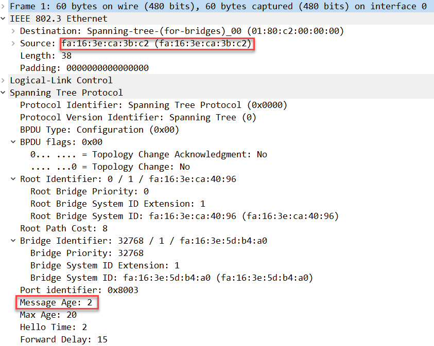
Between SW4 and SW5, only SW4 is forwarding BPDUs since the GigabitEthernet0/2 interface of SW5 is currently blocked. Here’s what the BPDU looks like:
Packet Capture: Spanning Tree Convergence SW4 SW5 BPDU
Our switches will keep flooding the BPDUs that you have seen above, as long as the topology remains the same. Time to stir up the hornet’s nest…
Reconvergence
We are going to shut one of the interfaces of SW1 so that the spanning tree topology changes. Some of our switches will lose their root ports. If we want to see everything in action, we’ll have to enable a debug:
SW1, SW2, SW3, SW4 & SW5
#debug spanning-tree events
Spanning Tree event debugging is on
Shutting GigabitEthernet0/1 on SW1
We will start by shutting the GigabitEthernet0/1 interface on SW1:
SW1(config)#interface GigabitEthernet 0/1
SW1(config-if)#shutdown
All of our switches will produce some debug info; let’s look at them one by one. We start with SW1:
SW1#
02:50:32: STP: VLAN0001 we are the spanning tree root
02:50:32: STP[1]: Generating TC trap for port GigabitEthernet0/1
02:50:52: STP: VLAN0001 Topology Change rcvd on Gi0/2
02:50:52: STP: VLAN0001 Topology Change rcvd on Gi0/2/code>
SW1 is the root bridge and generates a topology change trap, nothing else happens here. You can see this event occurs at 2:50:32.
Let’s check SW2:
SW2#
02:51:09: STP: VLAN0001 heard root 32769-fa16.3e5d.b4a0 on Gi0/2
02:51:09: STP: VLAN0001 Topology Change rcvd on Gi0/2
02:51:09: STP: VLAN0001 sent Topology Change Notice on Gi0/1
02:51:10: STP: VLAN0001 heard root 32769-fa16.3e5d.b4a0 on Gi0/2
02:51:10:     supersedes 32769-fa16.3e95.a9c9
02:51:10: STP: VLAN0001 new root is 32769, fa16.3e5d.b4a0 on port Gi0/2, cost 4
02:51:10: STP: VLAN0001 sent Topology Change Notice on Gi0/2
02:51:11: STP: VLAN0001 heard root     1-fa16.3eca.4096 on Gi0/2
02:51:11:     supersedes 32769-fa16.3e5d.b4a0
02:51:11: STP: VLAN0001 new root is 1, fa16.3eca.4096 on port Gi0/2, cost 16
SW2 is no longer receiving BPDUs from SW1, so it has to select another root port. You can see it is receiving a BPDU from SW4 (fa16.3e5d.b4a0), which claims that it is the new root bridge, superseding SW2 as the root bridge (fa16.3e95.a9c9).
For a short while, SW2 and SW4 are both isolated from receiving BPDUs from SW1 since SW5 is not forwarding any BPDUs on its blocked interface. About a second later, SW2 does receive the superior BPDU that is originated from SW1 and uses this as the root port.
The new root port was discovered at 02:51:11 so it took about 39 seconds.
Below, you can see the BPDU that SW2 generated when it thought it was the new root bridge:
And here’s the BPDU from SW4 who claimed to be the new root bridge:
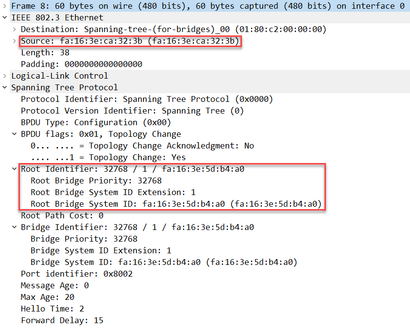
Packet Capture: Spanning Tree Convergence SW2 SW4 BPDU Scenario 1
Let’s check SW3:
SW3#
02:50:38: STP: VLAN0001 Topology Change rcvd on Gi0/2
02:50:38: STP: VLAN0001 sent Topology Change Notice on Gi0/1
02:51:05: STP: VLAN0001 Topology Change rcvd on Gi0/2
02:51:05: STP: VLAN0001 sent Topology Change Notice on Gi0/1
Nothing much happens on SW3. This makes sense it’s root and designated ports didn’t change when GigabitEthernet0/1 on SW1 went down.
Packet Capture: Spanning Tree Convergence SW1 SW3 BPDU Scenario 1
Let’s check SW4:
SW4#
02:51:10: STP: VLAN0001 heard root     1-fa16.3eca.4096 on Gi0/1
02:51:10:     supersedes 32769-fa16.3e5d.b4a0
02:51:10: STP: VLAN0001 new root is 1, fa16.3eca.4096 on port Gi0/1, cost 8
02:51:10: STP: VLAN0001 sent Topology Change Notice on Gi0/1
02:51:11: STP: VLAN0001 Topology Change rcvd on Gi0/1
02:51:11: STP: VLAN0001 heard root     1-fa16.3eca.4096 on Gi0/2
02:51:11:     supersedes 32769-fa16.3e5d.b4a0
02:51:11: STP: VLAN0001 new root is 1, fa16.3eca.4096 on port Gi0/2, cost 12
02:51:11: STP: VLAN0001 sent Topology Change Notice on Gi0/2
SW4 was temporarily thinking that it was the new root bridge since it doesn’t receive BPDUs from SW5. Within the same second, SW2 has sent the superior BPDU from SW1 so for a short while, SW4 reconsiders Gi0/1 as its root port. Once SW5 starts forwarding BPDUs, SW4 will use this interface as its root port.
Packet Capture: Spanning Tree Convergence SW4 SW5 BPDU Scenario 1
Last but not least, here’s SW5:
SW5#
02:50:43: STP: VLAN0001 Gi0/2 -> listening
02:50:45: STP: VLAN0001 Topology Change rcvd on Gi0/2
02:50:45: STP: VLAN0001 sent Topology Change Notice on Gi0/1
02:50:58: STP: VLAN0001 Gi0/2 -> learning
02:51:13: STP[1]: Generating TC trap for port GigabitEthernet0/2
02:51:13: STP: VLAN0001 sent Topology Change Notice on Gi0/1
02:51:13: STP: VLAN0001 Gi0/2 -> forwarding
SW5 is not receiving any superior BPDUs anymore from SW1 on its GigabitEthernet0/2 interface. This causes it to leave blocking mode, entering the listening and learning state, ending in forwarding mode.
Here’s the BPDU that SW5 forwards to SW4:
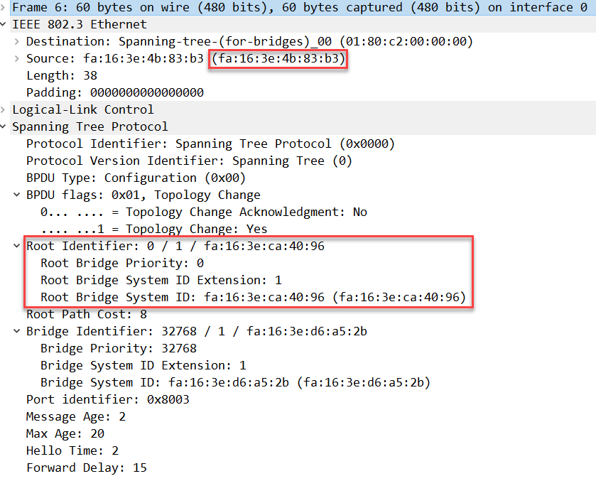
Packet Capture: Spanning Tree Convergence SW4 SW5 BPDU Scenario 1
For the sake of completeness, here’s an overview with the new interface states:
SW1#show spanning-tree | begin Interface
Interface           Role Sts Cost      Prio.Nbr Type
------------------- ---- --- --------- -------- --------------------------------
Gi0/2 Desg FWD 4 128.3 P2pSW2#show spanning-tree | begin Interface
Interface Role Sts Cost Prio.Nbr Type
------------------- ---- --- --------- -------- --------------------------------
Gi0/1 Desg FWD 4 128.2 P2p
Gi0/2 Root FWD 4 128.3 P2pSW3#show spanning-tree | begin Interface
Interface Role Sts Cost Prio.Nbr Type
------------------- ---- --- --------- -------- --------------------------------
Gi0/1 Root FWD 4 128.2 P2p
Gi0/2 Desg FWD 4 128.3 P2pSW4#show spanning-tree | begin Interface
Interface Role Sts Cost Prio.Nbr Type
------------------- ---- --- --------- -------- --------------------------------
Gi0/1 Desg FWD 4 128.2 P2p
Gi0/2 Root FWD 4 128.3 P2pSW5#show spanning-tree | begin Interface
Interface Role Sts Cost Prio.Nbr Type
------------------- ---- --- --------- -------- --------------------------------
Gi0/1 Root FWD 4 128.2 P2p
Gi0/2 Desg FWD 4 128.3 P2pOur topology now looks like this:
Shutting GigabitEthernet0/2 on SW1
Let’s try something else. We will start again with the topology where both interfaces on SW1 are in forwarding mode. I’m going to shut the GigabitEthernet 0/2 interface this time:
SW1(config)#interface GigabitEthernet 0/2
SW1(config-if)#shutdown
Here’s what happens on SW1:
SW1#
03:00:01: STP: VLAN0001 we are the spanning tree root
03:00:01: STP[1]: Generating TC trap for port GigabitEthernet0/2
03:00:20: STP: VLAN0001 Topology Change rcvd on Gi0/1
03:00:50: STP: VLAN0001 Topology Change rcvd on Gi0/1
SW1 is the root bridge, generating a TCP trap.
Let’s check SW2:
SW2#
03:00:40: STP: VLAN0001 Topology Change rcvd on Gi0/2
03:00:40: STP: VLAN0001 sent Topology Change Notice on Gi0/1
03:01:09: STP: VLAN0001 Topology Change rcvd on Gi0/2
03:01:09: STP: VLAN0001 sent Topology Change Notice on Gi0/1
Nothing interesting happens on SW2 since its root port remains the same.
Packet Capture: Spanning Tree Convergence SW1 SW2 BPDU Scenario 2
Here’s SW3:
SW3#
03:00:05: STP: VLAN0001 heard root     1-fa16.3eca.4096 on Gi0/2
03:00:05:     supersedes 32769-fa16.3e65.f2bc
03:00:05: STP: VLAN0001 new root is 1, fa16.3eca.4096 on port Gi0/2, cost 16
03:00:05: STP: VLAN0001 sent Topology Change Notice on Gi0/2
SW3 loses its root port and for a short moment, it sees itself as the root bridge before it receives the superior BPDU from SW1 on its Gigabit0/2 interface. This becomes its new root port. Here’s the BPDU when SW3 saw itself as the root bridge:
Packet Capture: Spanning Tree Convergence SW3 SW5 BPDU Scenario 2
Let’s check SW4:
SW4#
03:00:47: STP: VLAN0001 Topology Change rcvd on Gi0/2
03:00:47: STP: VLAN0001 sent Topology Change Notice on Gi0/1
03:01:16: STP: VLAN0001 Topology Change rcvd on Gi0/2
03:01:16: STP: VLAN0001 sent Topology Change Notice on Gi0/1
Nothing much happens on SW4. It’s root and designated ports remain the same.
Packet Capture: Spanning Tree Convergence SW2 SW4 BPDU Scenario 2
Last but not least, here’s SW5:
SW5#
03:00:12: STP: VLAN0001 new root port Gi0/2, cost 12
03:00:12: STP: VLAN0001 Gi0/2 -> listening
03:00:13: STP: VLAN0001 heard root 32769-fa16.3e65.f2bc on Gi0/1
03:00:13: STP: VLAN0001 Topology Change rcvd on Gi0/1
03:00:13: STP: VLAN0001 sent Topology Change Notice on Gi0/2
03:00:27: STP: VLAN0001 Gi0/2 -> learning
03:00:42: STP[1]: Generating TC trap for port GigabitEthernet0/2
03:00:42: STP: VLAN0001 sent Topology Change Notice on Gi0/2
03:00:42: STP: VLAN0001 Gi0/2 -> forwarding
SW5 is no longer receiving BPDUs from SW1 on its GigabitEthernet 0/1 interface so it loses its root port (GigabitEthernet0/1) and it has to figure out which interface will become the new root port. Since SW3 temporarily claimed itself as the root bridge, SW5 is receiving this BPDU.
It is also receiving the superior BPDU from SW1 on its GigabitEthernet 0/2 interface so this interface will move from the blocking state to the listening, learning and forwarding state. This becomes the new root port.
Packet Capture: Spanning Tree Convergence SW3 SW5 BPDU Scenario 2
Packet Capture: Spanning Tree Convergence SW4 SW5 BPDU Scenario 2
Here’s an overview with the new port states:
SW1#show spanning-tree | begin Interface
Interface           Role Sts Cost      Prio.Nbr Type
------------------- ---- --- --------- -------- --------------------------------
Gi0/1 Desg FWD 4 128.3 P2pSW2#show spanning-tree | begin Interface
Interface Role Sts Cost Prio.Nbr Type
------------------- ---- --- --------- -------- --------------------------------
Gi0/2 Desg FWD 4 128.2 P2p
Gi0/1 Root FWD 4 128.3 P2pSW3#show spanning-tree | begin Interface
Interface Role Sts Cost Prio.Nbr Type
------------------- ---- --- --------- -------- --------------------------------
Gi0/2 Root FWD 4 128.2 P2pSW4#show spanning-tree | begin Interface
Interface Role Sts Cost Prio.Nbr Type
------------------- ---- --- --------- -------- --------------------------------
Gi0/2 Desg FWD 4 128.2 P2p
Gi0/1 Root FWD 4 128.3 P2pSW5#show spanning-tree | begin Interface
Interface Role Sts Cost Prio.Nbr Type
------------------- ---- --- --------- -------- --------------------------------
Gi0/2 Root FWD 4 128.2 P2p
Gi0/1 Desg FWD 4 128.3 P2pAnd the topology now looks like this:
Only one comment:
-Second scenary: BPDUs between SW2 and SW4: “Since SW2 temporarily claimed itself as the root bridge”, it should say “Since SW3 temporarily claimed itself as the root bridge”. Let me get to knoe im a mistake, thanks.
rEgards
Jose
Hello Jose
Yes as far as I can see you are correct. I will let @ReneMolenaar know to change it.
Thanks!
Laz
Hi guys,
two questions:
When the root bridge looses a connection like in the example shown, why does it not send a TCN?
Why only a TC trap is generated? It lost one of its designated ports. Or is that not a topology change from the roots perspective?
When a new root port is elected on a switch and the new root port is the former designated port, there is now listening/learning/forwarding process happening, right? Because the port did that already and is already in a “forwarding” state!? Only if a port is in blocking state or the port just came UP, correct?
Thanks!
Hello Florian
Question 1
The Root bridge never sends out TCNs because a TCN is used primarily to inform the root bridge of the topology change. More accurately, it is used to inform all switches between the topology change and the root bridge of the change. If a topology change occurs on the actual root bridge, it doesn’t need to send a TCN based on the above description. Note the following Cisco documentation:
https://www.cisco.com/c/en/us/support/switches/retired.html
Question 2
... Continue reading in our forumWhen a port changes from Designated port (forwarding state) to root port (also
Hi Laz,
thanks a lot for your answer!
I thought it might be faster for the root bridge to send a BPDU with the TC bit set right away when it realizes that a link is down, instead of waiting to hear from other switches in the network through a TCN and then sending the BPDU with the TC set.
Got it
I have two more questions.
-
... Continue reading in our forumJust read the “Spanning-Tree UplinkFast” article and at one point the ND port changes to become the new root port, but it only goes through listening/learning/forwarding. I thought a ND equals a blocking port and thus needs to wait 20s