Lesson Contents
IS-IS as a link-state routing protocol requires that all routers in the same area (or backbone) have a synchronized link-state database. When a router floods its LSP carrying its prefixes, it’s important that all routers that receive it somehow acknowledge this. This introduces a problem on multi-access networks like a LAN. Let me give you an example:
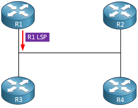
Above we have four routers connected to a LAN segment. These routers will send hello packets to each other and when they see other routers, they will become neighbors. In IS-IS, all routers establish a full neighbor adjacency with each other (unlike OSPF where routers only form a full neighbor adjacency with the DR/BDR). Once the routers are neighbors, they will flood their LSP to a multicast destination; all other routers will receive this LSP and add it to their database. Above we see that R1 floods its LSP on the LAN.
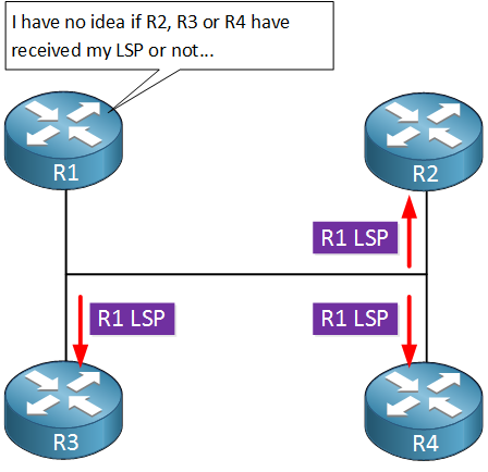
The LSP from R1 might make it to R2, R3, and R4 but there is no way for R1 to know. We need an acknowledgment so that R1 knows that its LSP made it to the other routers. We could let R2, R3, and R4 send a unicast acknowledgment to R1 but that’s not how IS-IS works.
Another issue is that the link-state database can grow exponentially. With four routers on a LAN, each router will have three neighbor adjacencies. There will be six neighbor adjacencies to consider in total.
To solve the acknowledgment problem and to reduce the size of the link-state database, we use a special mechanism. When IS-IS routers become neighbors, they also do an election to decide who becomes the DIS (Designated IS). The decision which becomes the DIS is based on certain criteria:
- Interface priority (default 64)
- highest SNPA (Subnetwork Point of Attachment)
- On a LAN, this is the MAC address.
- On frame-relay, this is the DLCI number.
- If the DLCI number is the same, the system ID is the tie-breaker.
We can change the priority, but by default, on a LAN the router with the highest MAC address will become the DIS. There is only one DIS, there is no backup router, and the election is preemptive. If you configure a router with a better priority or one that has a higher MAC address, it will become the new DIS immediately.
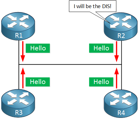
The DIS is responsible for creating a pseudonode. This is a virtual node created by the DIS. The pseudonode will do two things:
- Create and update a pseudonode LSP that reports links to all neighbors.
- Create a CSNP (Complete Sequence Numbers Protocol).
The pseudonode will send the pseudonode LSP that contains a list of all neighbors that it is connected to with a metric of 0. This pseudonode LSP is sent to a multicast address, all IS-IS routers receive it. This turns the multi-access network into a “point-to-point” topology where the pseudonode sits in the middle:
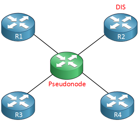
This simplifies the link-state topology There are now only four neighbor adjacencies to consider:
- R1-Pseudonode
- R2-Pseudonode
- R3-Pseudonode
- R4-Pseudonode
Which is far less than the six neighbor adjacencies we would have without the pseudonode where each router would report three neighbor adjacencies.
The second task of the pseudonode is to create a CSNP:
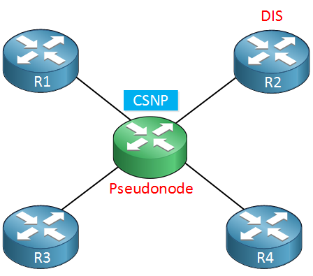
In the CSNP we will find a summary of each LSP that was flooded in the area:
- LSP ID
- LSP sequence number
- LSP remaining lifetime
- LSP checksum
You won’t find any prefixes in the CSNP. It’s just a simple overview with the latest LSPs. Why do we use this? Here’s an example:
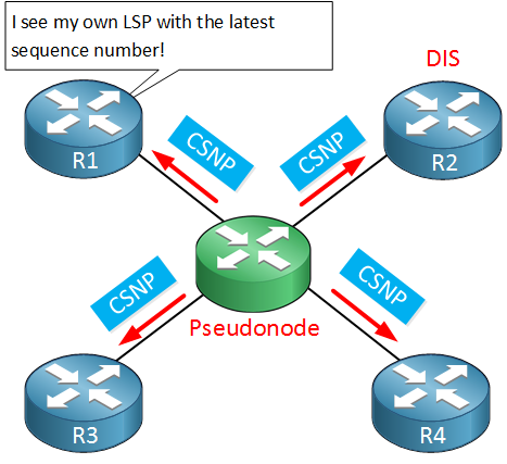
Previously, R1 has flooded its LSP on the LAN but didn’t know if R2, R3 or R4 received it or not. It now sees the CSNP from the pseudonode which includes a summary of the LSP from R1. This acts like an acknowledgment, R1 now knows that the pseudonode has seen its LSP.
What if R1 doesn’t see its own LSP in the CSNP? That tells R1 that the LAN doesn’t know about its LSP and it will flood its LSP again.
If one of the routers receives the CSNP and sees that one of the LSPs in the CSNP has a higher sequence number than the one in its own database, then it will send a PSNP (Partial Sequence Numbers PDU), requesting the newer information. The PSNP is sent with multicast so all routers receive it. Only the DIS will respond to this message. We do this because if all routers would respond, we would waste network resources.
The CSNP is sent every 10 seconds so there will be plenty of opportunities for the routers to check if their latest LSP is known on the LAN and if their current information is up-to-date.
Configuration
Let’s take a look at the DIS and pseudonode in action. I will use the following topology for this example:
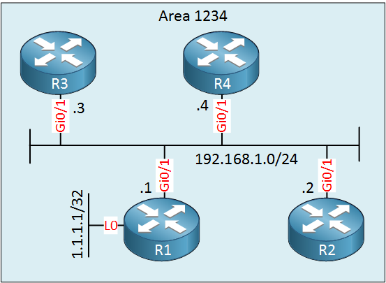
Above we have four routers that are connected to a single switch. We use the 192.168.1.0/24 subnet. R1 has a loopback that I will use to trigger it to update its LSP. I will configure all routers as level 1 routers.
Configurations
Want to take a look for yourself? Here you will find the startup configuration of each device.
R1
hostname R1
!
ip cef
!
interface Loopback0
 ip address 1.1.1.1 255.255.255.255
 ip router isis
!
interface GigabitEthernet0/1
 ip address 192.168.1.1 255.255.255.0
 ip router isis
!
router isis
 net 49.1234.0000.0000.0001.00
 is-type level-1
 log-adjacency-changes
!
end
R2
hostname R2
!
ip cef
!
interface GigabitEthernet0/1
 ip address 192.168.1.2 255.255.255.0
 ip router isis
!
router isis
 net 49.1234.0000.0000.0002.00
 is-type level-1
 log-adjacency-changes
!
end
R3
hostname R3
!
ip cef
!
interface GigabitEthernet0/1
 ip address 192.168.1.3 255.255.255.0
 ip router isis
!
router isis
 net 49.1234.0000.0000.0003.00
 is-type level-1
 log-adjacency-changes
!
end
R4
hostname R4
!
ip cef
!
interface GigabitEthernet0/1
 ip address 192.168.1.4 255.255.255.0
 ip router isis
!
router isis
 net 49.1234.0000.0000.0004.00
 is-type level-1
 log-adjacency-changes
!
end
Verification
Let’s start by looking at the neighbor adjacencies:
R1#show isis neighbors

System Id       Type Interface     IP Address      State Holdtime Circuit Id
R2              L1   Gi0/1         192.168.1.2     UP    9        R2.01
R3              L1   Gi0/1         192.168.1.3     UP    28       R2.01
R4 L1 Gi0/1 192.168.1.4 UP 27 R2.01R2#show isis neighbors
System Id Type Interface IP Address State Holdtime Circuit Id
R1 L1 Gi0/1 192.168.1.1 UP 22 R2.01
R3 L1 Gi0/1 192.168.1.3 UP 28 R2.01
R4 L1 Gi0/1 192.168.1.4 UP 27 R2.01R3#show isis neighbors
System Id Type Interface IP Address State Holdtime Circuit Id
R1 L1 Gi0/1 192.168.1.1 UP 22 R2.01
R2 L1 Gi0/1 192.168.1.2 UP 9 R2.01
R4 L1 Gi0/1 192.168.1.4 UP 27 R2.01R4#show isis neighbors
System Id Type Interface IP Address State Holdtime Circuit Id
R1 L1 Gi0/1 192.168.1.1 UP 21 R2.01
R2 L1 Gi0/1 192.168.1.2 UP 9 R2.01
R3 L1 Gi0/1 192.168.1.3 UP 28 R2.01In the output above, we see that we have a full-mesh of neighbor adjacencies. Each router has become neighbors with all other routers. The other thing we see is the circuit ID. The circuit ID is a one octet value that uniquely identifies the interface that IS-IS runs on. On a multi-access network, the circuit ID is concatenated with the system ID of the DIS. Looking at the value (R2.01), this tells us that R2 must be the DIS.
Once the routers are neighbors, they will flood their LSPs. Here’s an example of the LSP that R1 floods:
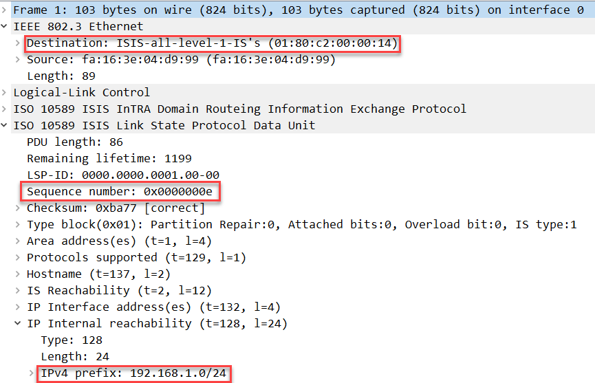
Above you can see that the LSP gets flooded to 01:80:c2:00:00:14, the multicast address for all level 1 IS-IS routers.
Here’s the pseudonode LSP that R2, our DIS floods:
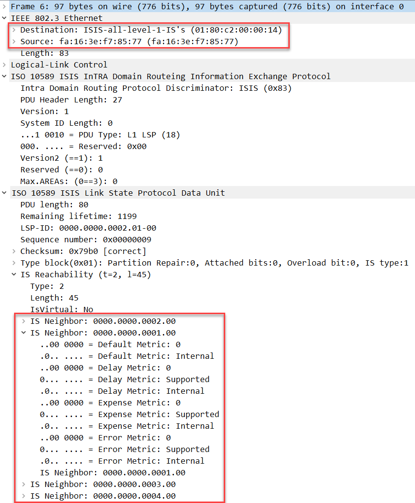
Above you can see an overview of all neighbors that are connected (including R2) to the pseudonode with a metric of 0.
Let’s take a look at the databases of our routers:
R1#show isis database

IS-IS Level-1 Link State Database:
LSPID                 LSP Seq Num  LSP Checksum  LSP Holdtime      ATT/P/OL
R1.00-00            * 0x0000000E   0x6CFB        1151              0/0/0
R2.00-00              0x0000000B   0x9ACD        430               0/0/0
R2.01-00              0x00000009   0x7BAF        935               0/0/0
R3.00-00              0x0000000C   0xC0A3        624               0/0/0
R4.00-00 0x0000000C 0xE878 643 0/0/0R2#show isis database
IS-IS Level-1 Link State Database:
LSPID LSP Seq Num LSP Checksum LSP Holdtime ATT/P/OL
R1.00-00 0x0000000E 0x6CFB 1149 0/0/0
R2.00-00 * 0x0000000B 0x9ACD 434 0/0/0
R2.01-00 * 0x00000009 0x7BAF 938 0/0/0
R3.00-00 0x0000000C 0xC0A3 625 0/0/0
R4.00-00 0x0000000C 0xE878 644 0/0/0R3#show isis database
IS-IS Level-1 Link State Database:
LSPID LSP Seq Num LSP Checksum LSP Holdtime ATT/P/OL
R1.00-00 0x0000000E 0x6CFB 1149 0/0/0
R2.00-00 0x0000000B 0x9ACD 434 0/0/0
R2.01-00 0x00000009 0x7BAF 937 0/0/0
R3.00-00 * 0x0000000C 0xC0A3 629 0/0/0
R4.00-00 0x0000000C 0xE878 646 0/0/0R4#show isis database
IS-IS Level-1 Link State Database:
LSPID LSP Seq Num LSP Checksum LSP Holdtime ATT/P/OL
R1.00-00 0x0000000E 0x6CFB 1149 0/0/0
R2.00-00 0x0000000B 0x9ACD 432 0/0/0
R2.01-00 0x00000009 0x7BAF 936 0/0/0
R3.00-00 0x0000000C 0xC0A3 626 0/0/0
R4.00-00 * 0x0000000C 0xE878 647 0/0/0The database of each router is the same. We can see an LSP for R1, R2, R3, and R4. The second LSP that you see (R2.01-00) is the pseudonode LSP, generated by R2 our DIS. Let’s take a look at one of the regular LSPs. For example, the LSP of R1:
R1#show isis database R1.00-00 detail


IS-IS Level-1 LSP R1.00-00
LSPID                 LSP Seq Num  LSP Checksum  LSP Holdtime      ATT/P/OL
R1.00-00            * 0x0000000E   0x7CF3        637               0/0/0
  Area Address: 49.1234
  NLPID:        0xCC
  Hostname: R1
  Metric: 10         IS R2.01
  IP Address:   192.168.1.1
  Metric: 10         IP 192.168.1.0 255.255.255.0
Above we see two entries:
- Prefix 192.168.1.0/24 with a metric of 10.
- One entry for the pseudonode, with a metric of 10.
Let’s now take a look at the LSP of the pseudonode:
R1#show isis database R2.01-00 detail


IS-IS Level-1 LSP R2.01-00
LSPID                 LSP Seq Num  LSP Checksum  LSP Holdtime      ATT/P/OL
R2.01-00              0x00000009   0x85AA        1178              0/0/0
  Metric: 0          IS R2.00
  Metric: 0          IS R1.00
  Metric: 0          IS R3.00
  Metric: 0          IS R4.00
In the pseudonode LSP, we find an entry for each neighbor with a metric of 0.
What about the CSNP? It is sent by the pseudonode every 10 seconds. Here’s what this packet looks like:
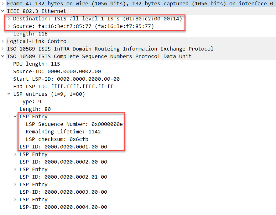
Above you can see that it is destined to 01:80:c2:00:00:14, this is a multicast address that is destined to all level 1 IS-IS routers. The source address is the MAC address of R2. In the LSP entries, we find a summary of each LSP that was flooded on the LAN. The one I highlighted is the LSP that R1 has flooded. There is no prefix information here; we only see the LSP-ID (R1), the sequence number, remaining lifetime, and checksum.
Packet Capture: IS-IS L1 DIS Pseudonode CSNP
Let’s see what happens when something changes. I’m going to activate IS-IS on the loopback interface of R1:
R1(config)#interface Loopback 0
R1(config-if)#ip router isis
This will trigger R1 to update and flood its LSP. Here’s what the LSP of R1 looks like in Wireshark:
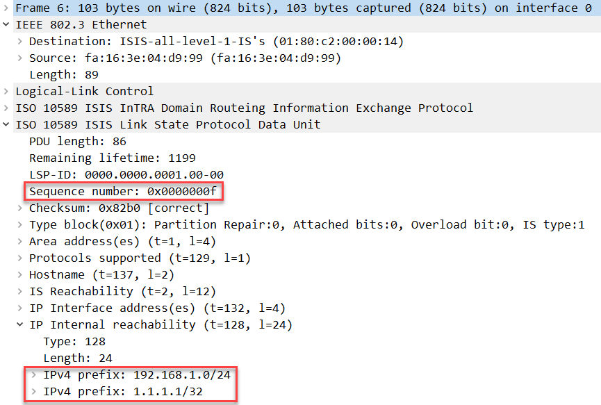
Above we see that the sequence number for the LSP has increased from 0x0000000E to 0x0000000F and that prefix 1.1.1.1/32 was added. All routers that receive this LSP will update it in their database. R2, our DIS and responsible for the pseudonode will update its CSNP:
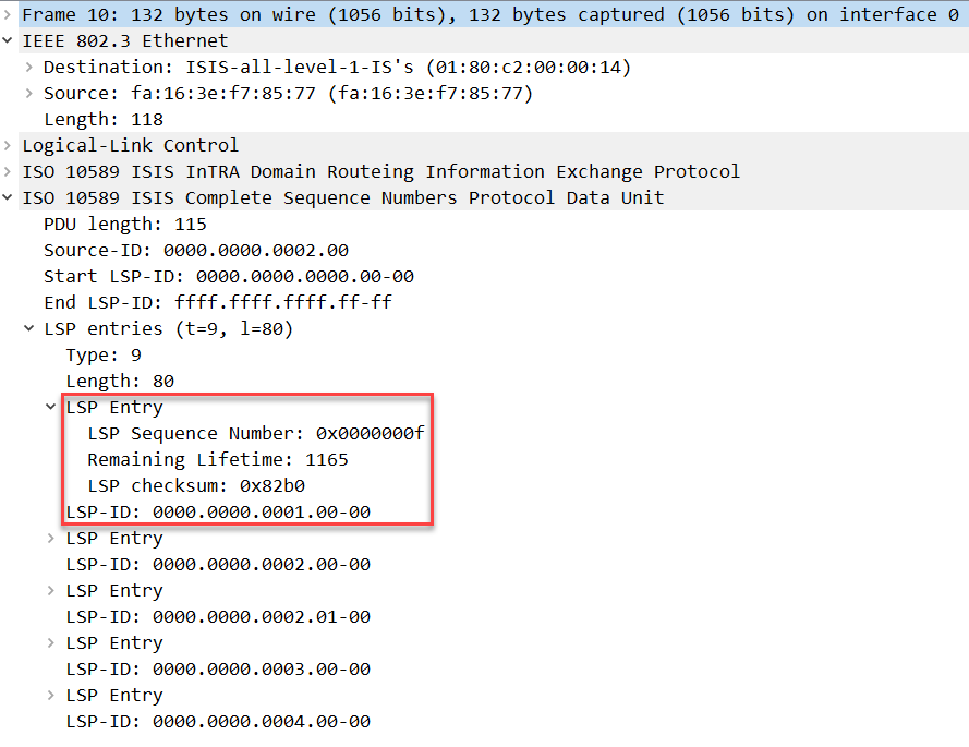
Above we see the new sequence number in the CSNP that the pseudonode floods every 10 seconds. You can see the new sequence number in the database of each router:
R1#show isis database

IS-IS Level-1 Link State Database:
LSPID                 LSP Seq Num  LSP Checksum  LSP Holdtime      ATT/P/OL
R1.00-00            * 0x0000000F   0x82B0        1182              0/0/0
R2.00-00              0x0000000B   0x9ACD        393               0/0/0
R2.01-00              0x00000009   0x7BAF        899               0/0/0
R3.00-00              0x0000000C   0xC0A3        587               0/0/0
R4.00-00 0x0000000C 0xE878 607 0/0/0R2#show isis database
IS-IS Level-1 Link State Database:
LSPID LSP Seq Num LSP Checksum LSP Holdtime ATT/P/OL
R1.00-00 0x0000000F 0x82B0 1180 0/0/0
R2.00-00 * 0x0000000B 0x9ACD 397 0/0/0
R2.01-00 * 0x00000009 0x7BAF 901 0/0/0
R3.00-00 0x0000000C 0xC0A3 589 0/0/0
R4.00-00 0x0000000C 0xE878 608 0/0/0R3#show isis database
IS-IS Level-1 Link State Database:
LSPID LSP Seq Num LSP Checksum LSP Holdtime ATT/P/OL
R1.00-00 0x0000000F 0x82B0 1180 0/0/0
R2.00-00 0x0000000B 0x9ACD 398 0/0/0
R2.01-00 0x00000009 0x7BAF 901 0/0/0
R3.00-00 * 0x0000000C 0xC0A3 593 0/0/0
R4.00-00 0x0000000C 0xE878 610 0/0/0R4#show isis database
IS-IS Level-1 Link State Database:
LSPID LSP Seq Num LSP Checksum LSP Holdtime ATT/P/OL
R1.00-00 0x0000000F 0x82B0 1180 0/0/0
R2.00-00 0x0000000B 0x9ACD 396 0/0/0
R2.01-00 0x00000009 0x7BAF 900 0/0/0
R3.00-00 0x0000000C 0xC0A3 589 0/0/0
R4.00-00 * 0x0000000C 0xE878 610 0/0/0Just in case one of our routers missed the initial LSP flooding of R1, they will see they have an outdated LSP once they receive the CSNP. This allows them to request the new LSP from the DIS with a PSNP and update their database.
I captured this process in Wireshark. You can see the initial CSNP, the updated LSP from R1 when the loopback is advertised and the updated CSNP from the pseudonode:
Packet Capture: IS-IS Pseudonode New LSP
The last thing I’d like to show you is how to change the DIS. We can change the priority on any of our routers, and it will be effective immediately. Let’s make R4 our new DIS. Here’s how:
R4(config-if)#isis priority ?
  <0-127>  Priority value
Let’s change it to 100:
R4(config-if)#isis priority 100You can use the show isis neighbor command, but this time, I will use the show clns is-neighbor. The output is similar, but it will show you the priority:
R1#show clns is-neighbor
System Id       Interface     State  Type Priority  Circuit Id         Format
R2              Gi0/1         Up     L1   64        R4.01              Phase V
R3              Gi0/1         Up     L1   64        R4.01              Phase V
R4              Gi0/1         Up     L1   100       R4.01              Phase V
Above you can see the priority of R4. The new circuit ID (R4.01) tells us that R4 is now the DIS. We can also verify this by looking at the database:
R1#show isis database level-1

IS-IS Level-1 Link State Database:
LSPID                 LSP Seq Num  LSP Checksum  LSP Holdtime      ATT/P/OL
R1.00-00            * 0x00000012   0xB27B        1062              0/0/0
R2.00-00              0x0000000F   0xC899        1060              0/0/0
R2.01-00              0x0000000C   0xD11E        0 (1072)          0/0/0
R3.00-00              0x00000010   0xEE6F        1060              0/0/0
R4.00-00              0x00000010   0x1744        1060              0/0/0
R4.01-00              0x00000001   0x44EC        1060              0/0/0
Above we see the new pseudonode LSP (R4.01-00). The one from R2 is still visible but will removed after a while. Let’s take a closer look:


Hi Rene,
Is there any way to make it P2P like OSPF ? Thanks
br//zaman
Hello Zaman,
There is yes, you can use this command:
You can use this on broadcast networks (like Ethernet) when you only have two routers. This disables the creation/election of a DIS so it’s more efficient.
Rene
Hello Rene
i have Problem with understanding that DIS / PSN
please explain it to me more simple
Hello BGP
With the pseudonode, there are a total of four adjacencies in the whole topology. If there were no pseudonode, each router would have to create an adjacency with every other router. That means:
So by using the pseudonode you reduce the number of adjacencies, you reduce the complexity of the topology, and you reduce the number of updates that have to be exchanged between particular routers.
... Continue reading in our forumHello Kevin
When implementing OSPF, if there are many routers connected to the same broadcast domain, a DR and BDR election takes place. All routers in the broadcast domain create two neighbor adjacences: One to the DR and one to the BDR. There is also an adjacency between the DR and BDR.
When implementing IS-IS, there is a similar mechanism. The Designated IS (DIS) is elected and it creates a virtual router called a pseudonode. This pseudonode plays the corresponding role of the DR in OSPF. However, in this case, each router will create a single neighbor
... Continue reading in our forum