Lesson Contents
In this lesson we’ll take a look how to configure a MPLS Layer 3 VPN PE-CE scenario. Here’s the topology I will use:
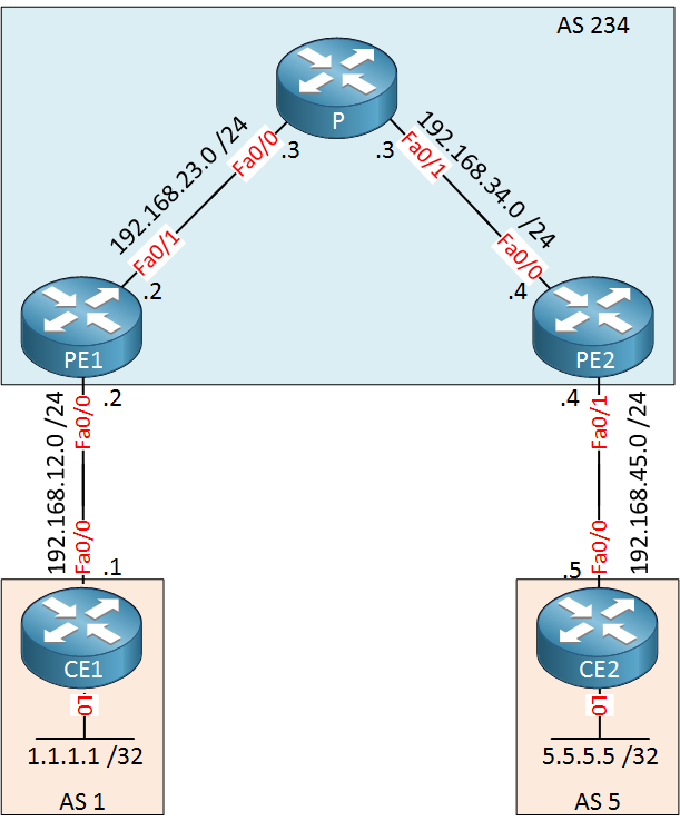
Above we have five routers where AS 234 is the service provider. There’s one customer with two sites, AS 1 and AS 5. Our customer wants to exchange 1.1.1.1 /32 and 5.5.5.5 /32 between its sites using BGP. To achieve this, we’ll have to do a couple of things:
- Configure IGP and LDP within the service provider network.
- Configure VRFs on the PE routers.
- Configure IBGP between the PE routers.
- Configure BGP between the PE and CE routers.
There are a lot of difference pieces in the MPLS puzzle to make this work. Instead of configuring everything at once and praying that it will work, we’ll build this network step-by-step. At each step, I’ll show you how to verify that it’s working before we continue with the next step.
Having said that, let’s get started!
Configuration
IGP and LDP
First we will configure the service provider network. On the PE1, P and PE2 routers we will create a loopback interface that will be advertised in OSPF. LDP will then uses the addresses as the transport address for the TCP connection. Let’s add those interfaces and enable OSPF:
PE1(config)#interface loopback 0
PE1(config-if)#ip address 2.2.2.2 255.255.255.255P(config)#interface loopback 0
P(config-if)#ip address 3.3.3.3 255.255.255.255PE2(config)#interface loopback 0
PE2(config-if)#ip address 4.4.4.4 255.255.255.255Now we will configure OSPF to advertise all interfaces in the service provider network:
PE1(config)#router ospf 1
PE1(config-router)#network 192.168.23.0 0.0.0.255 area 0
PE1(config-router)#network 2.2.2.2 0.0.0.0 area 0P(config)#router ospf 1
P(config-router)#network 192.168.23.0 0.0.0.255 area 0
P(config-router)#network 192.168.34.0 0.0.0.255 area 0
P(config-router)#network 3.3.3.3 0.0.0.0 area 0PE2(config)#router ospf 1
PE2(config-router)#network 192.168.34.0 0.0.0.255 area 0
PE2(config-router)#network 4.4.4.4 0.0.0.0 area 0And let’s enable LDP on all internal interfaces:
PE1(config)#interface FastEthernet 0/1
PE1(config-if)#mpls ipP(config)#interface FastEthernet 0/0
P(config-if)#mpls ip
P(config)#interface FastEthernet 0/1
P(config-if)#mpls ipPE2(config)#interface FastEthernet 0/0
PE2(config-if)#mpls ipThat takes care of that. Let’s see if MPLS is enabled:
PE1#show mpls interfaces
Interface              IP            Tunnel   BGP Static Operational
FastEthernet0/1 Yes (ldp) No No No YesP#show mpls interfaces
Interface IP Tunnel BGP Static Operational
FastEthernet0/0 Yes (ldp) No No No Yes
FastEthernet0/1 Yes (ldp) No No No YesPE2#show mpls interfaces
Interface IP Tunnel BGP Static Operational
FastEthernet0/0 Yes (ldp) No No No YesThat’s looking good to me. Do we have any LDP neighbors?
P#show mpls ldp neighbor
    Peer LDP Ident: 2.2.2.2:0; Local LDP Ident 3.3.3.3:0
	TCP connection: 2.2.2.2.646 - 3.3.3.3.55065
	State: Oper; Msgs sent/rcvd: 10/11; Downstream
	Up time: 00:02:39
	LDP discovery sources:
	  FastEthernet0/0, Src IP addr: 192.168.23.2
        Addresses bound to peer LDP Ident:
          192.168.12.2    192.168.23.2    2.2.2.2
    Peer LDP Ident: 4.4.4.4:0; Local LDP Ident 3.3.3.3:0
	TCP connection: 4.4.4.4.52817 - 3.3.3.3.646
	State: Oper; Msgs sent/rcvd: 10/11; Downstream
	Up time: 00:02:02
	LDP discovery sources:
	  FastEthernet0/1, Src IP addr: 192.168.34.4
        Addresses bound to peer LDP Ident:
          192.168.34.4    192.168.45.4    4.4.4.4
Our P router in the middle has two neighbors so we know that LDP is working. Just to be sure, let’s check if we have connectivity between PE1 and PE2:
PE1#ping 4.4.4.4 source loopback 0
Type escape sequence to abort.
Sending 5, 100-byte ICMP Echos to 4.4.4.4, timeout is 2 seconds:
Packet sent with a source address of 2.2.2.2
!!!!!
Success rate is 100 percent (5/5), round-trip min/avg/max = 1/2/4 ms
A quick ping tells us that it’s working. Are we switching based on labels though? Let’s do a trace to find out:
PE1#traceroute 4.4.4.4 source loopback 0
Type escape sequence to abort.
Tracing the route to 4.4.4.4
VRF info: (vrf in name/id, vrf out name/id)
  1 192.168.23.3 [MPLS: Label 17 Exp 0] 0 msec 0 msec 4 msec
  2 192.168.34.4 0 msec 0 msec *
Above you can see that we are using a label for the packet from PE1 to PE2. The P router is popping the label (penultimate hop popping) so PE1 receives a normal IP packet. So far, this is looking good.
VRF on the PE routers
Since we want our customer routes separated from the service provider’s routes, we’ll have to create some VRFs. Here’s how it’s done:
PE1(config)#ip vrf CUSTOMERFirst I will create a VRF called CUSTOMER. The next step will be configuring a RD (Route Distinguisher):
PE1(config-vrf)#rd ?
  ASN:nn or IP-address:nn  VPN Route Distinguisher
The RD is to make sure that all prefixes are unique. The customer prefix + RD together are a VPNv4 route. I’ll pick something simple:
PE1(config-vrf)#rd 1:1Our RD will be 1:1. The next item to configure is the RT (Route Target). This defines where we will import and export our VPNv4 routes. I want to make sure that all routes from CE1 and CE2 will be exchanged:
PE1(config-vrf)#route-target both 1:1I will use RT value 1:1 and use parameter both. This means that all routes of this VRF will be imported and exported.
Here’s what the VRF now looks like:
PE1#show run | begin vrf
ip vrf CUSTOMER
 rd 1:1
 route-target export 1:1
 route-target import 1:1
After creating the VRF globally, we have to assign the interface that is facing the customer to the VRF:
PE1(config)#interface FastEthernet 0/0
PE1(config-if)#ip vrf forwarding CUSTOMER
% Interface FastEthernet0/0 IPv4 disabled and address(es) removed due to enabling VRF CUSTOMER
Once you add an interface to a VRF, Cisco IOS will remove its IP address. Let’s add it again:
PE1(config-if)#ip address 192.168.12.2 255.255.255.0The VRF configuration of PE1 is now complete. We’ll configure the exact same thing on PE2:
PE2(config)#ip vrf CUSTOMER
PE2(config-vrf)#rd 1:1
PE2(config-vrf)#route-target export 1:1
PE2(config-vrf)#route-target import 1:1

PE2(config)#interface FastEthernet 0/1
PE2(config-if)#ip vrf forwarding CUSTOMER
PE2(config-if)#ip address 192.168.45.4 255.255.255.0
The VRFs are now configured. If you want to reach the CE1 or CE2 routers then you’ll have to use the VRFs from now on:
PE1#ping vrf CUSTOMER 192.168.12.1
Type escape sequence to abort.
Sending 5, 100-byte ICMP Echos to 192.168.12.1, timeout is 2 seconds:
!!!!!
Success rate is 100 percent (5/5), round-trip min/avg/max = 1/1/4 msPE2#ping vrf CUSTOMER 192.168.45.5
Type escape sequence to abort.
Sending 5, 100-byte ICMP Echos to 192.168.45.5, timeout is 2 seconds:
!!!!!
Success rate is 100 percent (5/5), round-trip min/avg/max = 1/2/4 msGreat our VRFs are operational!
IBGP Configuration on PE1 and PE2
PE1 and PE2 will have to exchange VPNv4 routes through IBGP. When you configure iBGP, your routers will only exchange IPv4 unicast routes by default. Since we need the PE routers to exchange VPNv4 routes, we’ll have to activate an additional address-family:
PE1(config)#router bgp 234
PE1(config-router)#neighbor 4.4.4.4 remote-as 234
PE1(config-router)#neighbor 4.4.4.4 update-source loopback 0
PE1(config-router)#address-family vpnv4
PE1(config-router-af)#neighbor 4.4.4.4 activate
In the configuration above I’m sourcing the iBGP updates from the loopback interface. We also enabled the VPNv4 address-family, this will allow the router to exchange those VPNv4 routes. When you activate the VPNv4 address-family, the router will do one more thing for you:
PE1#show run | section bgp
router bgp 234
 bgp log-neighbor-changes
 neighbor 4.4.4.4 remote-as 234
 neighbor 4.4.4.4 update-source Loopback0
 !
 address-family vpnv4
  neighbor 4.4.4.4 activate
  neighbor 4.4.4.4 send-community extended
 exit-address-family
Above you can see that the router automatically added the send-community extended command. This command is required and should never be removed since we use a community to advertise the route-target.
The configuration of PE1 is complete, let’s configure the same thing on PE2:
PE2(config)#router bgp 234
PE2(config-router)#neighbor 2.2.2.2 remote-as 234
PE2(config-router)#neighbor 2.2.2.2 update-source loopback 0
PE2(config-router)#address-family vpnv4
PE2(config-router-af)#neighbor 2.2.2.2 activate
The iBGP configuration of the PE routers is now complete. There’s one more thing we could do…
Right now our routers will be able to exchange IPv4 unicast prefixes and VPNv4 routes. In our example however, the PE routers will only be used to exchange VPNv4 routes so we can disable the address-family for IPv4 unicast. Here’s how you can do this:
PE1(config)#router bgp 234
PE1(config-router)#address-family ipv4
PE1(config-router-af)#no neighbor 4.4.4.4 activatePE2(config)#router bgp 234
PE2(config-router)#address-family ipv4
PE2(config-router-af)#no neighbor 2.2.2.2 activate This will disable the IPv4 unicast address-family. Let me show you the complete BGP configuration one more time:
PE1#show run | section bgp
router bgp 234
 bgp log-neighbor-changes
 neighbor 4.4.4.4 remote-as 234
 neighbor 4.4.4.4 update-source Loopback0
 !
 address-family ipv4
  no neighbor 4.4.4.4 activate
 exit-address-family
 !
 address-family vpnv4
  neighbor 4.4.4.4 activate
  neighbor 4.4.4.4 send-community extended
 exit-address-family
With this BGP configuration, we will use IPv4 to establish the neighbor adjacency but we won’t exchange IPv4 prefixes. The only thing we will exchange are VPNv4 routes.
Before we continue we should check if IBGP is working or not. You’ll need to use some different commands however, here’s why:
PE1#show ip bgp summary
The show ip bgp summary command won’t work since it is used to check IPv4 unicast prefixes. Here’s the command you need to use:
PE1#show bgp vpnv4 unicast all summary
BGP router identifier 2.2.2.2, local AS number 234
BGP table version is 1, main routing table version 1

Neighbor        V           AS MsgRcvd MsgSent   TblVer  InQ OutQ Up/Down  State/PfxRcd
4.4.4.4 4 234 7 7 1 0 0 00:03:03 0PE2#show bgp vpnv4 unicast all summary
BGP router identifier 4.4.4.4, local AS number 234
BGP table version is 1, main routing table version 1
Neighbor V AS MsgRcvd MsgSent TblVer InQ OutQ Up/Down State/PfxRcd
2.2.2.2 4 234 8 8 1 0 0 00:04:00 0You need to use the show bgp vpnv4 command to look at anything that is related to the VPNv4 address-family. Above you can see that PE1 and PE2 have become neighbors, nothing has been exchanged yet since we don’t have any VPNv4 routes right now.
EBGP on PE and CE
The last piece of the puzzle is exchanging routes between the PE and CE routers. In this example, we’ll use EBGP. Let’s start with the CE routers:
CE1(config)#interface loopback 0
CE1(config-if)#ip address 1.1.1.1 255.255.255.255

CE1(config)#router bgp 1
CE1(config-router)#neighbor 192.168.12.2 remote-as 234
CE1(config-router)#network 1.1.1.1 mask 255.255.255.255
And we’ll do something similar on CE2:
CE2(config)#interface loopback 0
CE2(config-if)#ip address 5.5.5.5 255.255.255.255

CE2(config)#router bgp 5
CE2(config-router)#neighbor 192.168.45.4 remote-as 234
CE2(config-router)#network 5.5.5.5 mask 255.255.255.255
The configuration of the CE routers is straight forward, this is plain and simple eBGP. Let’s configure the PE routers:
The interface that connects to the CE1 router is assigned to the VRF. This means we’ll have to create an address-family in BGP for this VRF:
PE1(config)#router bgp 234
PE1(config-router)#address-family ipv4 vrf CUSTOMER
PE1(config-router-af)#neighbor 192.168.12.1 remote-as 1
Let’s find out if we have established a BPG neighbor adjacency with the CE1 router:
PE1#show bgp vpnv4 unicast vrf CUSTOMER summary
BGP router identifier 2.2.2.2, local AS number 234
BGP table version is 2, main routing table version 2
1 network entries using 160 bytes of memory
1 path entries using 56 bytes of memory
2/1 BGP path/bestpath attribute entries using 272 bytes of memory
1 BGP AS-PATH entries using 24 bytes of memory
1 BGP extended community entries using 24 bytes of memory
0 BGP route-map cache entries using 0 bytes of memory
0 BGP filter-list cache entries using 0 bytes of memory
BGP using 536 total bytes of memory
BGP activity 1/0 prefixes, 1/0 paths, scan interval 60 secs

Neighbor        V           AS MsgRcvd MsgSent   TblVer  InQ OutQ Up/Down  State/PfxRcd
192.168.12.1    4            1      13      12        2    0    0 00:07:31        1
Great, we have become neighbors and we received one prefix. Let’s take a closer look to see what we have learned:
PE1#show bgp vpnv4 unicast vrf CUSTOMER
BGP table version is 2, local router ID is 2.2.2.2
Status codes: s suppressed, d damped, h history, * valid, > best, i - internal,
              r RIB-failure, S Stale, m multipath, b backup-path, x best-external, f RT-Filter
Origin codes: i - IGP, e - EGP, ? - incomplete

   Network          Next Hop            Metric LocPrf Weight Path
Route Distinguisher: 1:1 (default for vrf CUSTOMER)
*> 1.1.1.1/32       192.168.12.1             0             0 1 i
Above you can see that we have learned prefix 1.1.1.1 /32 and we will use RD 1:1. These two values together are our VPNv4 route.
Let’s configure PE2 to become neighbors with CE2:
PE2(config)#router bgp 234
PE2(config-router)#address-family ipv4 vrf CUSTOMER
PE2(config-router-af)#neighbor 192.168.45.5 remote-as 5
Let’s see if they have become neighbors:
PE2#show bgp vpnv4 unicast vrf CUSTOMER summary
BGP router identifier 4.4.4.4, local AS number 234
BGP table version is 4, main routing table version 4
2 network entries using 320 bytes of memory
2 path entries using 112 bytes of memory
3/2 BGP path/bestpath attribute entries using 408 bytes of memory
2 BGP AS-PATH entries using 48 bytes of memory
1 BGP extended community entries using 24 bytes of memory
0 BGP route-map cache entries using 0 bytes of memory
0 BGP filter-list cache entries using 0 bytes of memory
BGP using 912 total bytes of memory
BGP activity 2/0 prefixes, 2/0 paths, scan interval 60 secs

Neighbor        V           AS MsgRcvd MsgSent   TblVer  InQ OutQ Up/Down  State/PfxRcd
192.168.45.5    4            5       5       5        4    0    0 00:00:31        1
Great, PE2 and CE2 are now neighbors. Did we learn anything?
PE2#show bgp vpnv4 unicast vrf CUSTOMER
BGP table version is 4, local router ID is 4.4.4.4
Status codes: s suppressed, d damped, h history, * valid, > best, i - internal,
              r RIB-failure, S Stale, m multipath, b backup-path, x best-external, f RT-Filter
Origin codes: i - IGP, e - EGP, ? - incomplete

   Network          Next Hop            Metric LocPrf Weight Path
Route Distinguisher: 1:1 (default for vrf CUSTOMER)
*>i1.1.1.1/32       2.2.2.2                  0    100      0 1 i
*> 5.5.5.5/32       192.168.45.5             0             0 5 i
Interesting…above you see two prefixes. The first entry was learned through iBGP from the PE1 router. Take a close look at the next hop address which is 2.2.2.2.
Normally when you use iBGP between two routers, the next hop address does not change automatically. That’s why we use BGP next hop self sometimes to fix reachability issues. For VPNv4 routes however the next hop address is changed automatically because the loopback address of the other PE router will be the endpoint of the tunnel.
Everything is now in place, the only thing left to do is to verify our work.
Verification
I already showed you how to verify some of the things that we configured but there is still a couple of things to check. We need to make sure that there is connectivity between the CE routers and I will also show you how to check the transport and VPN labels that are used by the routers.
First we will check if our CE routers have learned anything through BGP:
CE1#show ip bgp
BGP table version is 3, local router ID is 1.1.1.1
Status codes: s suppressed, d damped, h history, * valid, > best, i - internal,
              r RIB-failure, S Stale, m multipath, b backup-path, x best-external, f RT-Filter
Origin codes: i - IGP, e - EGP, ? - incomplete

   Network          Next Hop            Metric LocPrf Weight Path
*> 1.1.1.1/32       0.0.0.0                  0         32768 i
*> 5.5.5.5/32 192.168.12.2 0 234 5 iCE2#show ip bgp
BGP table version is 3, local router ID is 5.5.5.5
Status codes: s suppressed, d damped, h history, * valid, > best, i - internal,
r RIB-failure, S Stale, m multipath, b backup-path, x best-external, f RT-Filter
Origin codes: i - IGP, e - EGP, ? - incomplete
Network Next Hop Metric LocPrf Weight Path
*> 1.1.1.1/32 192.168.45.4 0 234 1 i
*> 5.5.5.5/32 0.0.0.0 0 32768 iCE1 and CE2 have learned about each others networks. Let’s try a quick ping, just to check if things are working or note:
CE1#ping 5.5.5.5 source loopback 0
Type escape sequence to abort.
Sending 5, 100-byte ICMP Echos to 5.5.5.5, timeout is 2 seconds:
Packet sent with a source address of 1.1.1.1
!!!!!
Success rate is 100 percent (5/5), round-trip min/avg/max = 1/2/4 ms
Great, our ping is working! A trace is more interesting to look at however, it will show the transport and VPN label that we use:
CE1#traceroute 5.5.5.5 source loopback 0
Type escape sequence to abort.
Tracing the route to 5.5.5.5
VRF info: (vrf in name/id, vrf out name/id)
  1 192.168.12.2 0 msec 0 msec 4 msec
  2 192.168.23.3 [MPLS: Labels 17/19 Exp 0] 0 msec 0 msec 4 msec
  3 192.168.45.4 [MPLS: Label 19 Exp 0] 0 msec 0 msec 4 msec
  4 192.168.45.5 0 msec 0 msec *
Above you can see how the packet travels from CE1 to CE2:
- The CE1 router sends a normal IP packet to the PE1 router.
- The PE1 router will add two labels to it:
- First it will add the VPN label (19) which PE2 can use to determine to which VRF this packet will belong.
- The second label is the transport label (17) that is used to get this packet through the core of the service provider network.
- The P router will receive the packet, looks at the transport label, pops it and forwards the packet to the PE2 router.
- The PE2 router will look at the VPN label and decides that this is for VRF CUSTOMER. It will remove the label and forwards the IP packet to the CE2 router.
Let’s take a closer look at the labels that we use. Here’s how you can find the VPN label that the PE1 router will use for 5.5.5.5 /32:
PE1#show bgp vpnv4 unicast all 5.5.5.5
BGP routing table entry for 1:1:5.5.5.5/32, version 4
Paths: (1 available, best #1, table CUSTOMER)
  Advertised to update-groups:
     3
  5
    4.4.4.4 (metric 3) from 4.4.4.4 (4.4.4.4)
      Origin IGP, metric 0, localpref 100, valid, internal, best
      Extended Community: RT:1:1
      mpls labels in/out nolabel/19
The output above is interesting to look at. PE1 tells us that it has learned about 5.5.5.5 /32 in VRF CUSTOMER. The next hop address is 4.4.4.4 and the VPN label will be 19.
The funny thing though is that the next hop is unreachable in the VRF because it’s in the global routing table:
PE1#show ip route vrf CUSTOMER 4.4.4.4
Routing Table: CUSTOMER
% Network not in tablePE1#show ip route 4.4.4.4
Routing entry for 4.4.4.4/32
Known via "ospf 1", distance 110, metric 3, type intra area
Last update from 192.168.23.3 on FastEthernet0/1, 02:05:53 ago
Routing Descriptor Blocks:
* 192.168.23.3, from 4.4.4.4, 02:05:53 ago, via FastEthernet0/1
Route metric is 3, traffic share count is 1This is an exception for VPNv4, based on the transport label the router knows to use the global routing table to figure out where 4.4.4.4/32 is. Here’s a good way to see both labels and the logic of the PE1 router how it will reach the next hop:
PE1#show ip cef vrf CUSTOMER 5.5.5.5
5.5.5.5/32
  nexthop 192.168.23.3 FastEthernet0/1 label 17 19
Our PE1 router knows that in order to reach 5.5.5.5, it has to use 192.168.23.3 as the next hop (P router). In order to get there, we will use transport label value 17. This packet will be forwarded to the P router which checks its own forwarding table to figure out what to do with it:
P#show mpls forwarding-table
Local      Outgoing   Prefix           Bytes Label   Outgoing   Next Hop
Label      Label      or Tunnel Id     Switched      interface
16         Pop Label  2.2.2.2/32       21359         Fa0/0      192.168.23.2
17         Pop Label  4.4.4.4/32       21432         Fa0/1      192.168.34.4
When the P router receives something with label 17, it will pop the label and forwards it to 4.4.4.4 (PE2 router). Once PE2 receives it, it will check its forwarding table and finds this:
PE2#show mpls forwarding-table
Local      Outgoing   Prefix           Bytes Label   Outgoing   Next Hop
Label      Label      or Tunnel Id     Switched      interface
16         16         2.2.2.2/32       0             Fa0/0      192.168.34.3
17         Pop Label  3.3.3.3/32       0             Fa0/0      192.168.34.3
18         Pop Label  192.168.23.0/24  0             Fa0/0      192.168.34.3
19         No Label   5.5.5.5/32[V]    2498          Fa0/1      192.168.45.5
Anything that PE2 receives with label value 19 should have all its labels removed. This makes sense since CE2 doesn’t use MPLS, it uses regular IP forwarding. You can also see that 5.5.5.5 /32 is a VPN route. Once PE2 has removed all the labels, it forwards the IP packet to CE2 and that’s it.
Wireshark Captures
I figured it might be interesting to show you some wireshark captures of the things we discussed above. The first example is a BGP update where PE2 advertises the VPNv4 route for 5.5.5.5 /32 to PE1:
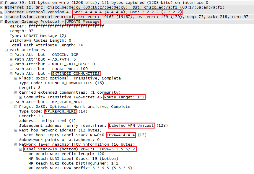
Above you can see quite some interesting items:
- In the extended communities you can find the route-target value 1:1
- In the NLRI information we find:
- The VPNv4 address-family.
- The next hop address 4.4.4.4.
- The VPN label value 19.
- The VPNv4 route:
- RD 1:1
- Prefix 5.5.5.5 /32
The second capture will show you what the packet from 1.1.1.1 to 5.5.5.5 looks like when we receive it on the P router:
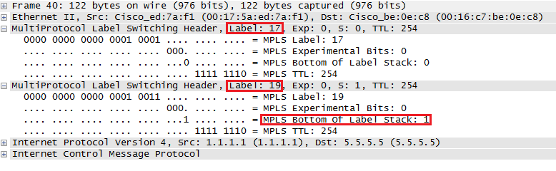
Above you see the ICMP request from CE1 to CE2, the first label is the transport label (17) and the second label is the VPN label which has the bottom of label stack bit set.
If you want to take a look for yourself, here are the links:
MPLS VPN transport and VPN label
Conclusion
That’s the end of this MPLS layer 3 VPN PE-CE configuration, if you understood everything and are able to configure this on your own then any of the other PE-CE scenarios will be no problem for you. In the next lessons I will show you how to configure PE-CE with OSPF and EIGRP.
Configurations
Want to take a look for yourself? Here are the final configurations of all devices.
CE1
hostname CE1
!
ip cef
!
interface Loopback0
 ip address 1.1.1.1 255.255.255.255
!
interface FastEthernet0/0
 ip address 192.168.12.1 255.255.255.0
 duplex auto
 speed auto
!
interface FastEthernet0/1
 no ip address
 shutdown
 duplex auto
 speed auto
!
router bgp 1
 bgp log-neighbor-changes
 network 1.1.1.1 mask 255.255.255.255
 neighbor 192.168.12.2 remote-as 234
!
end
PE1
hostname PE1
!
ip cef
!
ip vrf CUSTOMER
 rd 1:1
 route-target export 1:1
 route-target import 1:1
!
interface Loopback0
 ip address 2.2.2.2 255.255.255.255
!
interface FastEthernet0/0
 ip vrf forwarding CUSTOMER
 ip address 192.168.12.2 255.255.255.0
 duplex auto
 speed auto
!
interface FastEthernet0/1
 ip address 192.168.23.2 255.255.255.0
 duplex auto
 speed auto
 mpls ip
!
router ospf 1
 network 2.2.2.2 0.0.0.0 area 0
 network 192.168.23.0 0.0.0.255 area 0
!
router bgp 234
 bgp log-neighbor-changes
 neighbor 4.4.4.4 remote-as 234
 neighbor 4.4.4.4 update-source Loopback0
 !
 address-family ipv4
  no neighbor 4.4.4.4 activate
 exit-address-family
 !
 address-family vpnv4
  neighbor 4.4.4.4 activate
  neighbor 4.4.4.4 send-community extended
 exit-address-family
 !
 address-family ipv4 vrf CUSTOMER
  neighbor 192.168.12.1 remote-as 1
  neighbor 192.168.12.1 activate
 exit-address-family
!
end
P
hostname P
!
ip cef
!
interface Loopback0
 ip address 3.3.3.3 255.255.255.255
!
interface FastEthernet0/0
 ip address 192.168.23.3 255.255.255.0
 duplex auto
 speed auto
 mpls ip
!
interface FastEthernet0/1
 ip address 192.168.34.3 255.255.255.0
 duplex auto
 speed auto
 mpls ip
!
router ospf 1
 network 3.3.3.3 0.0.0.0 area 0
 network 192.168.23.0 0.0.0.255 area 0
 network 192.168.34.0 0.0.0.255 area 0
!
ip forward-protocol nd
no ip http server
no ip http secure-server
!
end
PE2
hostname PE2
!
ip vrf CUSTOMER
 rd 1:1
 route-target export 1:1
 route-target import 1:1
!
ip cef
!
interface Loopback0
 ip address 4.4.4.4 255.255.255.255
!
interface FastEthernet0/0
 ip address 192.168.34.4 255.255.255.0
 duplex auto
 speed auto
 mpls ip
!
interface FastEthernet0/1
 ip vrf forwarding CUSTOMER
 ip address 192.168.45.4 255.255.255.0
 duplex auto
 speed auto
!
router ospf 1
 network 4.4.4.4 0.0.0.0 area 0
 network 192.168.34.0 0.0.0.255 area 0
!
router bgp 234
 bgp log-neighbor-changes
 neighbor 2.2.2.2 remote-as 234
 neighbor 2.2.2.2 update-source Loopback0
 !
 address-family ipv4
  no neighbor 2.2.2.2 activate
 exit-address-family
 !
 address-family vpnv4
  neighbor 2.2.2.2 activate
  neighbor 2.2.2.2 send-community extended
 exit-address-family
 !
 address-family ipv4 vrf CUSTOMER
  neighbor 192.168.45.5 remote-as 5
  neighbor 192.168.45.5 activate
 exit-address-family
!
end
CE2
hostname CE2
!
ip cef
!
interface Loopback0
 ip address 5.5.5.5 255.255.255.255
!
interface FastEthernet0/0
 ip address 192.168.45.5 255.255.255.0
 duplex auto
 speed auto
!
router bgp 5
 bgp log-neighbor-changes
 network 5.5.5.5 mask 255.255.255.255
 neighbor 192.168.45.4 remote-as 234
!
end
If you have any questions, feel free to leave a comment!
Great stuff Rene Thanks for this!
Somehow, after seeing how it’s configured, it makes more sense now
This is all new to me, but since it’s explained in plain english again ..
Hi Rene,
Many thanks! Was reading the CiscoPress MPLS Fundamentals book, but it was taking too long to get to the point for MPLS L3 VPNs. This lesson was worth going through in a short time and now I know a lot more. I was able to work with GNS3 to try out the topology and everything worked perfectly. I will go back to the book to reinforce what I’ve learned here.
Thank you for breaking it down in plain English!
Best regards,
Shannon
Hi Shannon,
Glad to hear you like it! Now you know the basics, you’ll probably get a lot more value out of the book.
I noticed your idea about VPLS btw, I’ll add something soon.
Rene
Great as always. Just one minor issue. On the first topology picture, shouldnt the provider AS number be 123 as you stated in text instead of AS 234 or vice versa?
Hi Marcin,
Glad to hear you like it! Just changed the AS number, it should be 234.
Rene