Lesson Contents
Cisco’s Embedded Packet Capture (EPC) allows us to capture packets that flow to, through or from our router. Captures are stored in DRAM on the router where we can see a summary or detailed view of the packet(s). Since the captures are stored in DRAM, they’ll be gone after a reload. Optionally we can export our capture to an external server as a packet capture (PCAP) file so that we can open them with Wireshark.
EPC is available since IOS 12.4(20)T and IOS-XE 15.2(4)S – 3.7.0 or later.
These captures are stored in DRAM where we cand can be exported as capture files so that we can open and analyze them in Wireshark.
To configure EPC we have to do a couple of things:
- Configure a capture buffer: this is where the router stores the packets when they are captured.
- Configure a capture point: this is where we want to capture packets (interface and direction).
- Associate the capture buffer and capture point: this binds our capture buffer to the capture point.
- Start and stop the capture to get some packets.
- View the capture on the router (hex dump) or copy it to an external server so we can open it with Wireshark.
Let’s take a look how to do this!
Configuration
To demonstrate this I will use the following topology:
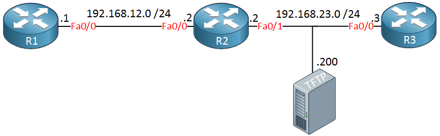
We will send a ping from R1 to R3 and capture these packets on R2. We can then export the captured packets to the TFTP server at 192.168.23.200. Here’s what the configuration looks like:
R2#monitor capture ?
  buffer  Control Capture Buffers
  point   Control Capture Points
We use the monitor capture command in privileged mode. I’ll start with the configuration of the capture buffer:
R2#monitor capture buffer ?
  WORD  Name of the Capture Buffer
First we have to think of a name, I’ll call my capture buffer “CAPTURE”:
R2#monitor capture buffer CAPTURE ?
  circular  Circular Buffer
  clear     Clear contents of capture buffer
  export    Export in Pcap format
  filter    Configure filters
  limit     Limit the packets dumped to the buffer
  linear    Linear Buffer(Default)
  max-size  Maximum size of element in the buffer (in bytes)
  size      Packet Dump buffer size (in Kbytes)
There’s a list of options. Let’s configure the size of our capture buffer:
R2#monitor capture buffer CAPTURE size ?
  <256-102400>  Buffer size in Kbytes : 102400K or less (default is 1024K)
The capture buffer is stored in DRAM so select whatever size you feel is appropriate. You can also specify the maximum size of a single packet:
R2#monitor capture buffer CAPTURE size 8192 max-size 2048 ?
  circular  Circular Buffer
  linear    Linear Buffer(Default)
I’ll use a capture buffer of 8192K and a single packet has a maximum size of 2048K. The last thing we have to decide is if we want to use a circular or linear buffer. The linear buffer will stop capturing once the buffer is full while the circular buffer keeps capturing and deletes the oldest packets from the buffer. Let’s go for the circular buffer:
R2#monitor capture buffer CAPTURE size 8192 max-size 2048 circularInstead of capturing all traffic, we’ll use a filter that only captures traffic from 192.168.12.1 to 192.168.23.3. Here’s how to configure it:
R2(config)#ip access-list extended PACKET_FILTER
R2(config-ext-nacl)#permit ip host 192.168.12.1 host 192.168.23.3

R2#monitor capture buffer CAPTURE filter access-list PACKET_FILTER
Filter Association succeeded
This attaches the access-list to our capture buffer. That’s all we have to do for the capture buffer so let’s configure the capture point so the router knows where to capture traffic:
R2#monitor capture point ?
  associate     Associate capture point with capture buffer
  disassociate  Dis-associate capture point from capture buffer
  ip            IPv4
  ipv6          IPv6
  start         Enable Capture Point
  stop          Disable Capture Point
Here you can see some of our options. Let’s select IPv4:
R2#monitor capture point ip ?
  cef               IPv4 CEF
  process-switched  Process switched packets
Here you have to decide between CEF or process switched packets. CEF is enabled by default so let’s go with that. Now we can choose the interface:

Thank You Rene, Cisco TAC used to do it and now I can do it
One thing that puzzles me about EPC is this seemingly artificial choice Cisco has you make between CEF and Process-switched methods. Why not just have it capture everything that traverses the interface in question? For example, I was trying to extend your example (and practice with extended ACLs) so that I would capture only BGP information being exchange between neighbors. I filtered on TCP 179 in both directions, and even threw in TCP established for good measure. No matter what I did, I would always capture zero packets. The only thing I can think of is
... Continue reading in our forumI thought about it some more, and, of course, the BGP traffic would be processed switched since it is destined for the router itself to be processed (stupid me). I still don’t know why it is necessary to specify whether you want the buffer to be CEF or Processed. Perhaps it is because traffic that would have normally been sent through CEF is now having to be punted so a copy can be placed in the EPC buffer.
Hi
Can we use the same method in nexus also ?
On NX-OS you can use Ethanalyzer:
https://community.cisco.com/t5/networking-knowledge-base/using-ethanalyzer-on-nexus-platform-for-control-plane-and-data/ta-p/3142665