CEF (Cisco Express Forwarding) polarization is an issue where the CEF hash algorithm selects certain paths in the network and leaves redundant paths unused. This is best explained with an example. Let’s take a look at the following topology:
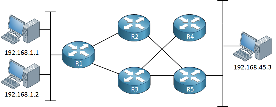
Above we have a topology with some routers. We have redundant links between R2, R3, R4, and R5. If we run an IGP like OSPF or EIGRP on this network and the metric is the same for all these links then we will use ECMP (Equal Cost MultiPath) routing. All interfaces in the network will be used:
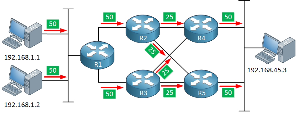
Our two hosts on the left side are sending 100 packets in total. R1 will load balance these so that R2 and R3 each receive 50 packets. R2 and R3 will use both interfaces, sending 25 packets on each interface. Finally, R4 and R5 each have 50 packets to deliver to H3.
This is not how it really works though. Cisco routers and switches use CEF which is responsible for forwarding traffic. CEF uses a hashing algorithm to decide which packets get sent on which interface. In its most basic form, CEF only considers the source and destination IP address to decide which interface will be used to forward traffic. When this occurs, the following situation might happen:
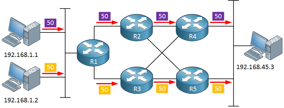
Above, H1 and H2 are sending 50 packets each. R1 runs its CEF hashing algorithm and decides that:
- packets from H1 (192.168.1.1) to H3 (192.168.45.3) should be forwarded using the interface that connects to R2.
- packets from H2 (192.168.1.2) to H3 (192.168.45.3) should be forwarded using the interface that connects to R3.
- Our packets are now load balanced between R2 and R3.
Our packets from H1 and H2 are now load balanced by R1 but when they reach R2 and R3, something interesting happens:
- R2 receives the packets from H1 and runs the same hashing algorithm as R1. Since it only receives packets from H1 to H3, a single interface is used for all these packets. The link between R2 and R5 will be unused.
- R3 receives the packets from H2 and runs the same hashing algorithm as R1. Since it only receives packets from H2 to H3, a single interface is used for all these packets. The link between R3 and R4 will be unused.
The process above is called CEF polarization, it’s the result of using the same hashing algorithm and same hash input on all routers. The result is that only one path is used in the network for a certain flow of packets.
CEF polarization can be avoided by using a different hashing algorithm. On modern IOS routers, the following hashing algorithm variations are available:
R1(config)#ip cef load-sharing ?
  algorithm  Per-destination load sharing algorithm selection

R1(config)#ip cef load-sharing algorithm ?
  include-ports  Algorithm that includes layer 4 ports
  original       Original algorithm
  tunnel         Algorithm for use in tunnel only environments
universal Algorithm for use in most environments- Original: the original variation of CEF only looks at the source and destination IP address. The router performs a XOR on the lower order bits of the source and destination IP address to decide which interface to use. When the source and destination addresses remain the same, the same interface will be picked.
- Universal: each router generates a unique 32 bit universal ID that is used as a seed in the hashing algorithm next to the source/destination IP addresses. Since each router will have a unique universal ID, each router will have a different hashing result and a different interface will be selected for each flow.
- Tunnel: this is an improvement to the universal algorithm meant for tunnel interfaces. With a tunnel interface, the source and destination are often the same so it’s possible that the same interface is used over and over again.
- L4 port: this variation includes the layer 4 source and/or destination port numbers in the hashing algorithm.
Only the original CEF variation is prone to CEF polarization, the other options avoid it by including other information besides the source/destination IP address.
Hi Rene,
Thanks for your very nice article.
Please clarify ""If we use different hashing algorithm then the flow will be considered based on different parameter but same flow will use the same link,Not possible any load balance using different hashing algorithm , right ??? and if we use “ip load-sharing per-packet” at interface level then all packet will push across all available link . we can influence Load Balance , right ??
So In summary…
- Different hashing algorithm : Only flow will be consider based on different parameter like Src IP/dst IP/L4 Port etc
... Continue reading in our forumHi Zaman,
What I mean by this is that for a single flow, the router always selects the same interface no matter the hash algorithm you use. The advantage of using a hash algorithm that uses more parameters is that you will have better load balancing since different flows will use different interfaces. For example, if you use a hashing algorithm that only includes source and destination IP address then it’s likely that the following flows will all get the same result and use the same outbound interface.
Here’s a quick example, let’s say we have these flows:
192.
... Continue reading in our forumHello Avid
When the term “flow” is used, it is referring to traffic that has the same source and destination address. So in both diagrams in the lesson, there are two flows: one from H1 to H3 and a second from H2 to H3.
Each router has a unique ID that is used for this algorithm. This means that for flow H1 to H2 for example, R1’s algorithm would send the flow via interface 1, R2s algorithm will send the flow
... Continue reading in our forumHi,
I’m a little confused by how polarisation is avoided.
I get that if you only use source and destination IP then all traffic between two hosts will take the same route, even if they are accessing different services (ports).
And I understand that if you include ports then the above problem is mitigated in that the traffic is will be spread more evenly amongst exit interfaces.
But, unless you use an algorithm that uses the random unique ID, wont polarisation always occur? Because the hash will always be the same. And the same exit interfaces will always be the
... Continue reading in our forumHello Samir
I understand what you’re saying here, and if you take a look at only two hosts communicating, then yes you are correct. The use of a unique ID won’t solve this problem. For this particula
... Continue reading in our forum