Lesson Contents
Precision Time Protocol (PTP) is a protocol to synchronize clocks in a computer network, similar to Network Time Protocol (NTP).
NTP is accurate, under ten milliseconds. PTP, however, is accurate up to less than a microsecond and is measured in nanoseconds. Why would you want this? NTP is fine for network clients such as desktops, laptops, or network monitoring. PTP is useful in scenarios where very accurate timing is required. For example:
- Energy providers for peak and off-peak billing rates.
- High-frequency trading.
- Manufacturing where robots in assembly lines work together and timing is important.
- Audio/video gear where real-time synchronization is important.
PTP can be used in these scenarios. One advantage of PTP is that if you already have Ethernet or IP, you can use your existing network for time synchronization. PTP can run directly over Ethernet or on top of IP with UDP for transport.
PTP is an IEEE/IEC standardized protocol defined in IEEE 1588, with multiple versions of PTP. The first version is from 2002, specified in IEEE 1588-2002. PTP Version 2 (PTPv2) was announced in IEEE 1588-2008. This version is not backward compatible with the 1588-2002 version. We now also have IEEE 1588-2019, known as PTPv2.1. This version is compatible with PTPv2 and adds some additional features.
Each industry has different requirements, which is why, besides the standard, there are different profiles. Here are some examples:
- Default PTP Profile:
- The default option.
- Telecom profile:
- Defined by the ITU-T under the G.8265.1, G.8275.1, and G.8275.2 recommendations. It’s used in telecommunication networks.
- Power profile:
- Defined under the IEEE C37.238 standard. It’s intended for power system applications, especially electric grid measurements and control.
- 802.1AS:
- Audio Video Bridging over Ethernet (AVB) is a set of standards that describe how to run real-time content such as audio and video over Ethernet networks. 802.1AS explains how to use PTP for AVB.
There are differences in how PTP is implemented between these profiles. For example:
- The default profile supports L2 and L3 transport. The power profile and 802.1AS only support L2 transport.
- The default profile and power profile support VLAN tagging. 802.1AS does not.
- The default profile allows non-PTP devices. The power profile and 802.1AS do not.
And there are other differences, such as how often they send messages, the clock types they support, etc.
When we want to synchronize clocks accurately up to nanoseconds, we have to deal with delays. For example:
- Propagation delay: The time it takes for an optical or electrical signal to travel through the wire.
- Queueing delay: The time a packet is delayed because of congestion or interface buffering.
- Processing delay: The time it takes to perform packet header error checking, routing table lookups, or switching a frame.
When one clock transmits the current time, it can be outdated the moment it is received by another clock. Luckily, PTP has a way to deal with this. Delay is inevitable, but we can measure, and PTP can compensate for it.
PTP works best when your hardware supports it. A NIC with PTP support has its own onboard clock, which is used to timestamp messages. You can run PTP in software without hardware support, but your OS will have to take care of timestamping. This negatively affects delay.
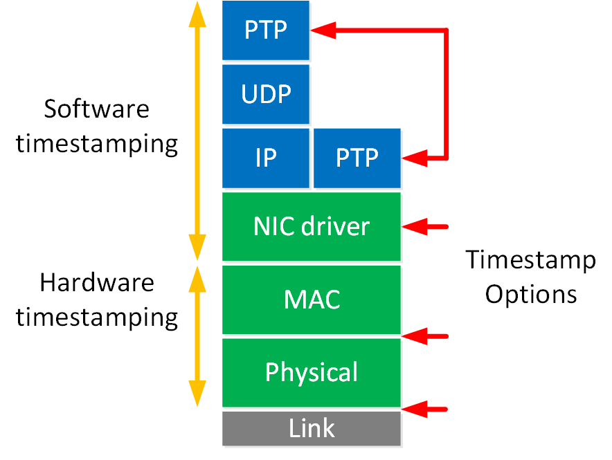
There are multiple options where you can timestamp. The closer to the physical layer, the more reliable and less delay you’ll see.
PTP uses the same epoch as Unix time (1 January 1970) but is based on International Atomic Time (TAI). The abbreviation is from the French name (Temps Atomique International). It’s not based on UTC. One of the reasons is that UTC is subject to leap seconds. PTP communicates the offset between TAI and UTC so that UTC can be calculated from the PTP time.
Clock Synchronization
To ensure clocks are synchronized correctly, PTP must measure the delay between two clocks. We have two clock roles. The time source has the master role, and the time receiver is the slave.
PTP synchronizes clocks by exchanging a couple of timestamped messages and storing the time we send and receive these messages. A slave clock calculates its delay and offset and updates its clock accordingly. Let’s look at how PTP synchronizes clocks. I’ll use a simple example with two clocks:
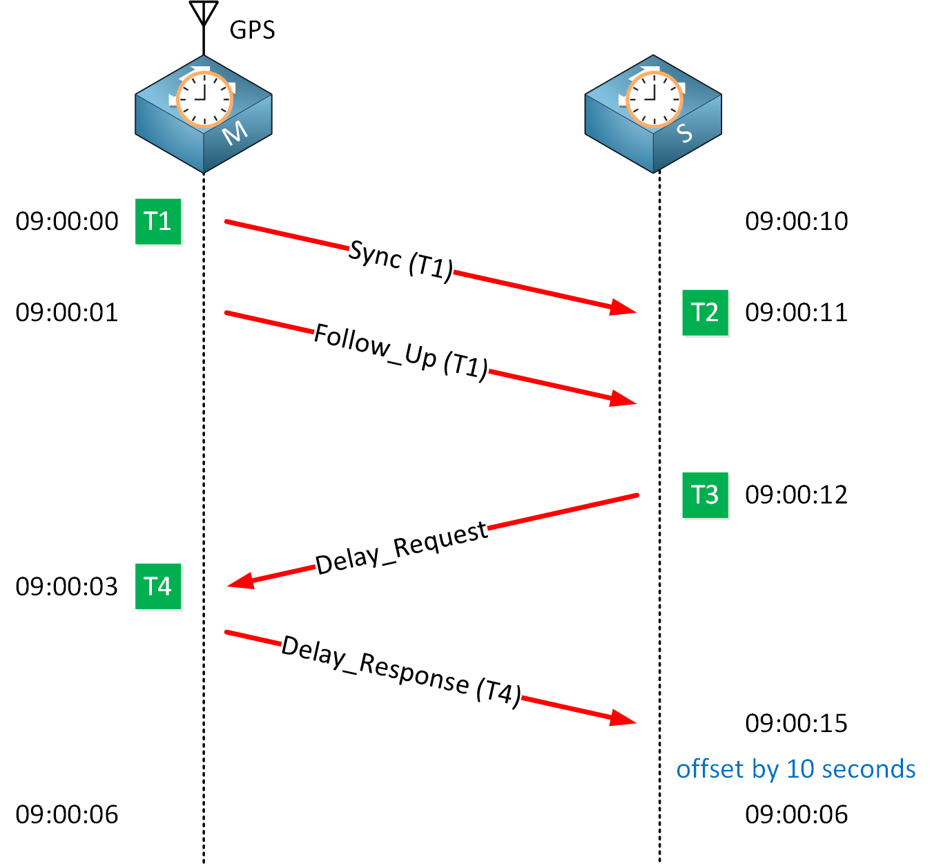
The master clock is at 9:00:00. The slave clock thinks it’s 9:00:10, so we have a 10-second offset. To keep it simple, we’ll imagine we have a one-second delay to transfer packets from the master to the slave clock.
The master periodically sends a sync message. Let’s say it sends a sync message at exactly 09:00:00. This moment is the T1 value. We now have two options:
- If your hardware supports PTP:
- The exchange is called a one-step message exchange, and we only send a sync message that contains the T1 value.
- If PTP is done in software:
- PTP uses a two-step message exchange because of additional delays.
- This means that after the sync message, we send a follow-up message immediately, including the T1 value.
- The T1 value won’t be in the sync message.
- The follow-up message means, “The sync message you just received was sent at the time specified in the T1 value”.
In my example, we use the two-step message exchange.
The slave clock stores the time it received the sync message as the T2 value. Its local clock believes it is 09:00:12. The slave clock now knows there is a 10-second difference between its local clock and the master clock. However, it can’t update itself yet because it doesn’t know how long it took to get a message from the master to the slave clock.
To synchronize itself correctly, it has to calculate two values:
- The delay of how long it takes to get the PTP messages from the master to the slave clock.
- The offset by which it has to update its clock.
Here are the two formulas to calculate these two values:
delay = ((t2 - t1) + (t4 - t3)) / 2offset = ((t2 - t1) - (t4 - t3)) / 2We have seen T1 and T2, but we haven’t seen T3 and T4 yet.
When the slave clock receives the follow-up message, it sends a delay request message. As the name implies, this message is used to determine the delay between the master and slave clock. The slave clock stores the time it sent this message as the T3 value. From the slave clock’s perspective, at 09:00:12.
Because of our one-second delay, the master clock receives it at 09:00:03. The master clock stores this moment as T4.
The master clock replies immediately with a delay response message that includes the T4 value. The slave clock now has four timestamps:
- T1:
- Included in the sync or follow-up message from the master clock:
- 09:00:00.
- Included in the sync or follow-up message from the master clock:
- T2:
- The moment in time we received the sync message, according to the slave clock:
- 09:00:11.
- The moment in time we received the sync message, according to the slave clock:
- T3:
- The moment in time when the slave clock sent the delay request message:
- 09:00:12.
- The moment in time when the slave clock sent the delay request message:
- T4:
- The moment in time the master clock receives the delay request message:
- 09:00:03.
- The moment in time the master clock receives the delay request message:
The slave clock can now calculate the offset relative to the master clock. The offset calculation assumes that the delay in propagating the message from the master to the slave clock is the same as the other way around. This is not always the case on Ethernet networks, though.
Let’s put everything in the delay and offset formula. Everything starts with 09:00, so we’ll focus on the seconds. Let’s start with delay. Here is the formula to calculate delay:
delay = ((t2 - t1) + (t4 - t3)) / 2Let’s add our numbers:
delay = ((11 - 0) + (3 - 12)) / 2Let’s break it down:
(11 - 0) = 11
(3 - 12) = -9
11 + -9 = 2
2 / 2 = 1
The delay is calculated as one second. Now, we’ll calculate the offset. Here is the formula:
offset = ((t2 - t1) - (t4 - t3)) / 2Let’s add our numbers:
offset = ((11 - 0) - (3 - 12)) / 2Let’s break it down:
(11 - 0) = 11
(3 - 12) = -9
11 - -9 = 20
20 / 2 = 10
The calculated offset is 10 seconds. The slave clock updates itself, offsetting its clock by 10 seconds. Network delay can change over time, so the master clock will keep sending sync messages.
PTP Clock Types
PTP has different clock types. Here is an overview:
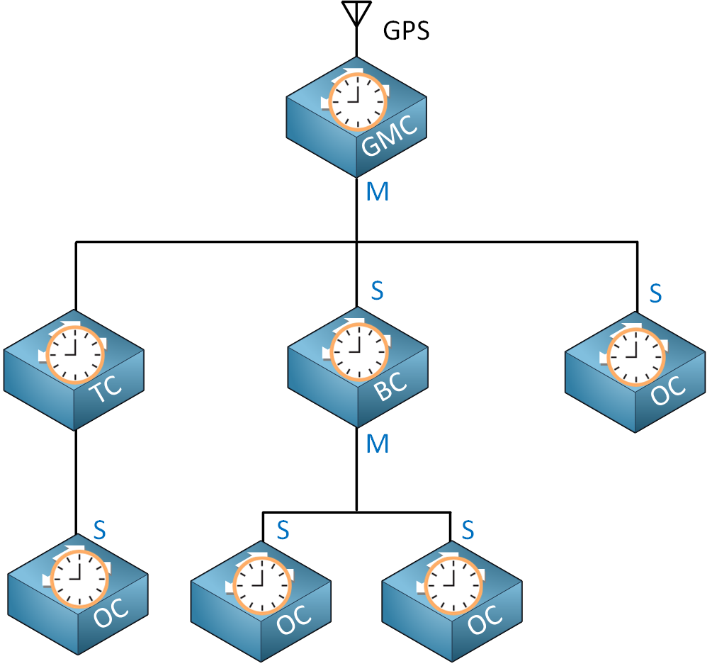
There are four clock types:
- Grandmaster clock (GMC)
- Ordinary clock (OC)
- Boundary clock (BC)
- Transparent clock (TC)
Besides the clock type, each interface can have the master (M) or slave (S) role. The master sends timing information, and the slave synchronizes itself. Depending on the clock type, an interface can have the master or slave role. It’s also possible that a clock has the master role on one interface and the slave role on another interface.
Let’s look at the different clock types.
Grandmaster Clock (GMC)
The grandmaster clock (GMC) is the primary source of time in PTP and is responsible for root timing reference. This clock is connected to a reliable time source, such as GPS or an atomic clock. All other clocks synchronize directly or indirectly with the grand master clock. The grandmaster clock always has the master role on its interface(s).
Ordinary Clock (OC)
The ordinary clock (OC) runs PTP on only one of its interfaces. This interface can have the slave or master role. This is usually an end device that needs its time synchronized.
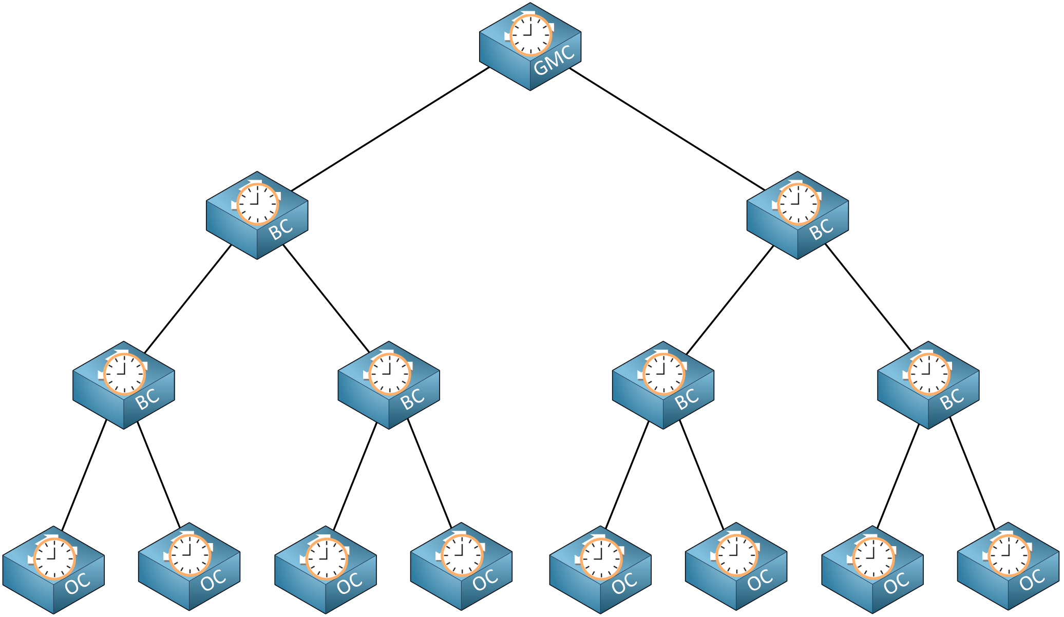
Boundary Clock (BC)
The boundary clock (BC) runs PTP on two or more interfaces. It can synchronize one network segment with another. The upstream interface that connects to the grandmaster clock has the slave role. The downstream interface that connects to other clocks has the master role.
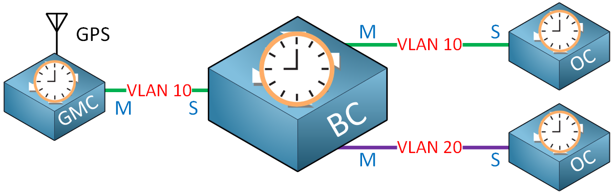
A boundary clock sits between the grandmaster clock and other boundary or ordinary clocks. Each interface can connect to a different VLAN to synchronize time in different VLANs. Adding boundary clocks to the network also has a scalability advantage because it prevents all ordinary clocks from having to talk with the grandmaster clock directly.
Each boundary clock syncs with an upstream clock and distributes time based on its local clock. This means that each clock depends on the quality of all upstream clocks. The more boundary clocks you add, the higher the chance your clocks are not as accurate anymore. Because of this, using boundary clocks is only suitable for networks with a small number of switches.
Transparent Clock (TC)
Transparent clocks (TC) were introduced in PTPv2, and their goal is to forward PTP messages. They can’t be a source clock like a grandmaster or boundary clock. They can forward PTP messages within a VLAN but not between VLANs.

The transparent clock can sit between the grandmaster clock and an ordinary clock. When we forward a PTP message through the transparent clock, the delay increases, which must be compensated. The transparent clock measures this delay and adds it to the correction field of a PTP message. This added time is called the residence time.
There are two transparent clock types:
- End-to-End Transparent Clock (E2E)
- Peer-to-Peer Transparent Clock (P2P)
Let’s check them out.
End-to-End Transparent Clock (E2E)
The end-to-end (E2) transparent clock sits between the grandmaster and the ordinary clock and transparently forwards PTP messages. Here’s what it looks like:
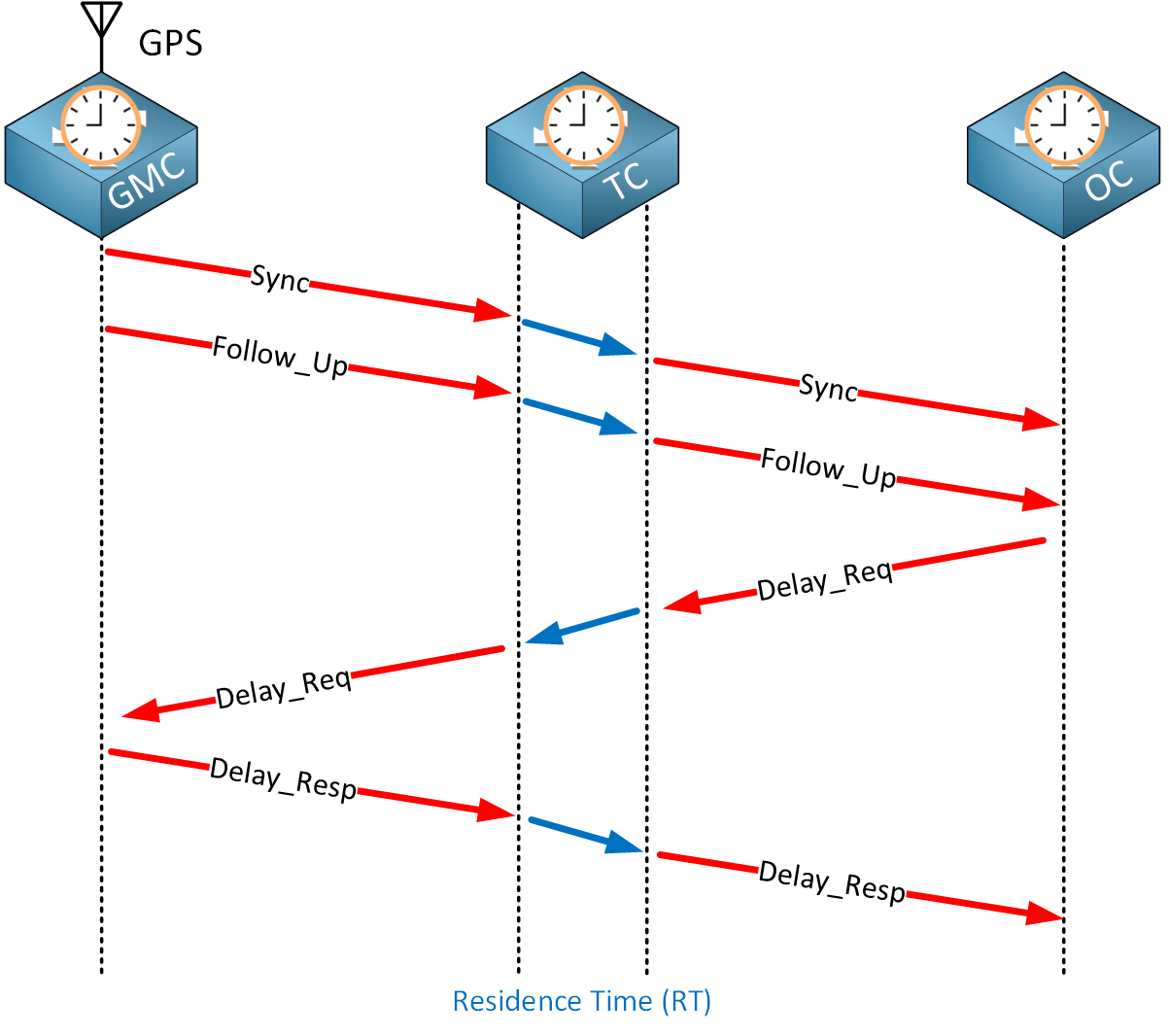
We see the same messages as those discussed in the clock synchronization section. The blue arrows indicate the time it takes for the transparent clock to forward these messages. This adds delay, and it must be compensated. Transparent clocks keep track of the time it takes to forward a PTP message. This is called the residence time (RT). Transparent clocks add this time in the correction field of PTP messages so that the ordinary clock can compensate for the delay.
Peer-to-Peer Transparent Clock (P2P)
The idea behind the peer-to-peer transparent clock (P2P) is that it’s better to calculate the delay for each interface than end-to-end. The P2p transparent clock calculates the delay from:
- The grandmaster clock to the transparent clock.
- The transparent clock to the ordinary clock.
Here’s what that looks like:
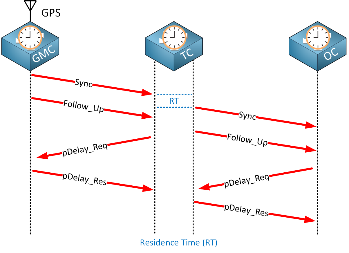
When a grandmaster clock sends a sync (and follow-up) message, the transparent clock forwards these messages to the ordinary clock. It also sends a peer delay request message to the grandmaster clock and receives a peer delay response message. The same peer delay message exchange occurs with the ordinary clock. This allows the transparent clock to figure out the delay on both interfaces. It also keeps track of the residence time and adds this in the correction field of PTP messages.
Scalability
Why would you pick E2E transparent clocks or P2P transparent clocks? Take a look at this picture:
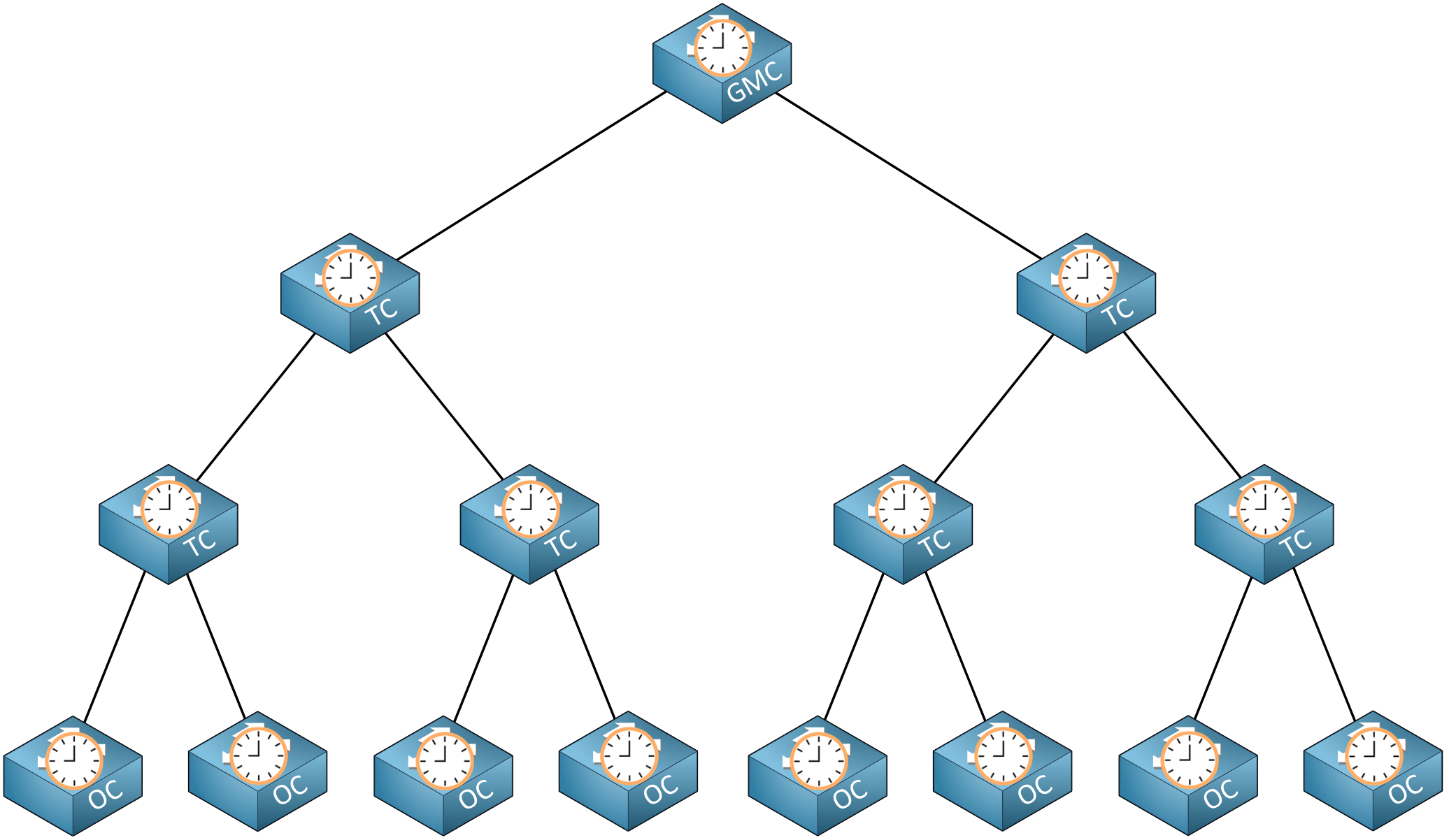
Above, we have a hierarchical network with PTP clocks. Imagine we have 500 ordinary clocks. If the transparent clocks were all E2E, the grandmaster clock would receive 500 delay request messages from all ordinary clocks. This doesn’t scale well.
With P2P transparent clocks, peer delay messages are only sent between one upstream or downstream clock. Peer-to-peer is more efficient because the delay is calculated on a single link, not end-to-end. Also, the ordinary clocks won’t send delay messages directly to the grandmaster clock.
Best Master Clock Algorithm (BMCA)
How do we define which clock becomes the master? We compare announce messages to determine which clock is the most accurate. We use the following order of items to determine the best master clock:
- Priority1:
- A value from 0-255 that you manually configure.
- Class:
- This tells what kind of source the clock has. The default value is 248. For example, a clock connected to GPS has class 6. When it loses its source, it becomes class 7.
- Accuracy:
- How accurate the clock is to the “true” time. Every clock, even an atomic clock, has some deviation from the actual time. The lower, the better.
- Variance:
- The stability of a clock. A clock can be accurate but could be unstable and drift over time. The lower, the better.
- Priority2:
- A value from 0-255 that you manually configure.
- Identity:
- An 8-byte number that is usually based on the device’s MAC address.
When the BMC algorithm finishes, the master clock sends sync messages at regular intervals. When a current master clock recognizes a new best master clock, it stops sending sync messages (or announce messages when using IEEE 1588-2008), and the new clock takes over as master.
PTP Messages
Throughout this lesson, I explained some of the PTP messages. It’s useful to have a complete overview of all PTP messages and their function. There are two message types:
- Event
- General
Let’s check out both.
Event
Event messages are time-critical. These are used to measure the time delay between clocks and are timestamped.
- Sync:
- The master clock periodically sends a sync message:
- With the one-step message exchange, this message contains the timestamp to tell the exact moment of its transmission. This is the T1 value.
- With the two-step message exchange, this message doesn’t contain a timestamp.
- The master clock periodically sends a sync message:
- Follow_Up:
- Shortly sent after the master clock after the sync message in the two-step message exchange. This contains the timestamp to tell when the sync message was transmitted. This is the T1 value.
- Delay_Req:
- The delay request message is sent from slave to master. This message is used to request the delay measurement.
- Delay_Resp:
- The delay response message from master to slave in response to the delay request message. This contains the timestamp with the T4 value.
General
General messages are not time-critical and don’t have timestamps. They are used to maintain PTP’s operation and manage the state of clocks.
- Announce:
- The grandmaster clock transmits this message and contains information about the clock, such as its quality, class, and accuracy.
- BMCA uses this message to determine the grandmaster clock.
- Management:
- This message is used to access the Management Information Base (MIB) of PTP devices.
- Signal:
- This message is used for non-time-critical communication between clocks. For example, it can communicate different signal intervals for sync or announce messages between clocks.
Configuration
Enough theory for now. Let’s look at PTP in action.
Hello Rene,
I am wondering why the multicast destination MAC address for the announce message in section 5.2.1 is not in the 01:00:5E range?
I thought all multicast frames at layer 2 always had a destination MAC address in the 01:00:5E range, but there its using a destination of 01:1b:19:00:00:00, can you please explain why its using that range if its a multicast frame?
Hello Paul
Indeed you are correct that the 01:00:5E range of MAC addresses is the range that is assigned for use with IPv4 multicast addresses. When you have an IPv4 multicast destination address, when encapsulation takes place, a specific mapping mechanism is used to map to this range. You can see this mechanism here:
https://networklessons.com/multicast/multicast-ip-address-to-mac-address-mapping
The Precision Time Protocol (PTP) however, does not use IP at all! It is a Layer 2 protocol. If you take a look at the packet captures in the lesson, you will se
... Continue reading in our forumHello,
I think there is a type in the Event messges, the last one should b Delay_Resp no?
David
Hello David
Yes, you are correct, I’ll let Rene know to make the correction. Thanks for that!
Laz
Hello Krishnamoorthi
The only way to definitely determine whether your hardware supports PTP (and whether it supports one-step or two-step sync) is to check with the manufacturer’s documentation. If the documentation doesn’t specify it you may need to contact the manufacturer for more details. \
I hope this has been helpful!
Laz