Lesson Contents
As we have seen in the IGMP snooping lesson, switches will listen to IGMP messages and learn on which interfaces they have to forward multicast traffic. Without IGMP snooping, switches will flood multicast traffic everywhere, treating it like broadcast traffic.
IGMP snooping works pretty well but it does require a multicast router in the network. When you want to implement it in a simple network, where you only have one VLAN and multiple switches, you can run into two possible issues:
- Multicast traffic gets flooded everywhere.
AND/OR - Some receivers don’t receive any multicast traffic.
In this lesson I will explain why IGMP snooping requires a multicast router, what happens when you don’t have one and how to solve it.
Configuration
Scenario with Multicast Router
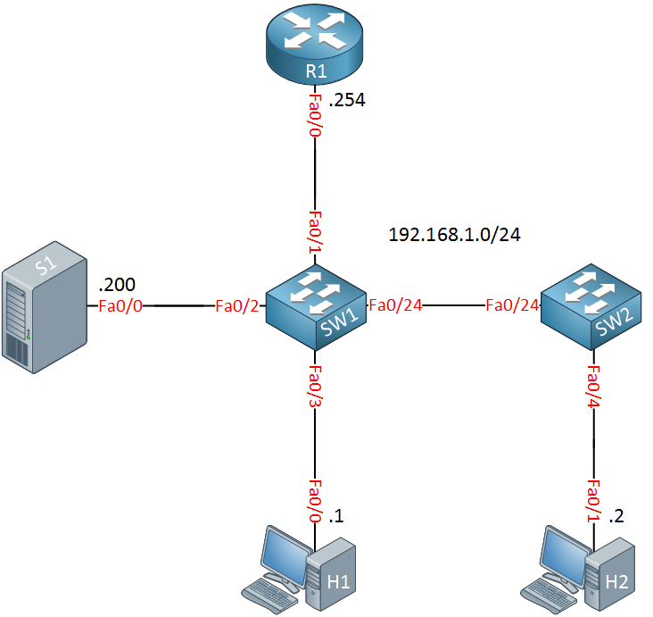
Let’s start with an example where do we have a multicast-enabled router. Here’s the topology that I will use:
 Above we have R1, our multicast router. H1 and H2 are receivers, S1 is the source. The two switches have IGMP snooping enabled by default and we are using default VLAN 1.
Configurations
Want to take a look for yourself? Here you will find the startup configuration of each device.
H1
hostname H1
!
ip cef
!
interface FastEthernet0/0
 ip address 192.168.1.1 255.255.255.0
!
end
H2
hostname H2
!
ip cef
!
interface FastEthernet0/1
 ip address 192.168.1.2 255.255.255.0
!
end
R1
hostname R1
!
ip cef
!
ip multicast-routing
!
interface FastEthernet0/0
 ip address 192.168.1.254 255.255.255.0
 ip pim sparse-mode
!
end
S1
hostname S1
!
ip cef
!
interface FastEthernet0/0
 ip address 192.168.1.200 255.255.255.0
!
end
SW1
hostname SW1
!
interface FastEthernet0/1
!
interface FastEthernet0/2
!
interface FastEthernet0/3
!
interface FastEthernet0/24
!
end
SW2
hostname SW2
!
interface FastEthernet0/4
!
interface FastEthernet0/24
!
end
Let’s make sure that IGMP snooping is enabled on both switches:
SW1#show ip igmp snooping | include snoop
IGMP snooping : EnabledSW2#show ip igmp snooping | include snoop
IGMP snooping : EnabledAnd let’s verify that both switches have learned the multicast router through its general queries:
SW1#show ip igmp snooping querier
Vlan      IP Address               IGMP Version   Port
-------------------------------------------------------------
1 192.168.1.254 v2 Fa0/1 SW2#show ip igmp snooping querier
Vlan IP Address IGMP Version Port
-------------------------------------------------------------
1 192.168.1.254 v2 Fa0/24 Everything is looking good. Before I configure the hosts to join a multicast group, let’s enable some debugs on the switches:
SW1#debug ip igmp snooping 239.1.1.1
group IP address debugging is on for 239.1.1.1SW2#debug ip igmp snooping 239.1.1.1
group IP address debugging is on for 239.1.1.1And on the hosts:
H1#debug ip igmp
IGMP debugging is onH2#debug ip igmp
IGMP debugging is onThis will allow us to see what is going on behind the scenes. Let’s configure H1 to join multicast group 239.1.1.1:
H1(config)#interface FastEthernet 0/0
H1(config-if)#ip igmp join-group 239.1.1.1
On H1 we can see that it generates a membership report for 239.1.1.1:
H1#
IGMP(0): WAVL Insert group: 239.1.1.1 interface: FastEthernet0/0Successful
IGMP(0): Send v2 Report for 239.1.1.1 on FastEthernet0/0
IGMP(0): Received v2 Query on FastEthernet0/0 from 192.168.1.254
IGMP(0): Set report delay time to 2.2 seconds for 239.1.1.1 on FastEthernet0/0
IGMP(0): Send v2 Report for 239.1.1.1 on FastEthernet0/0
Here’s what happens on SW1 when it receives the report from H1:
SW1#
IGMPSN: group: Received IGMPv2 report for group 239.1.1.1 received on Vlan 1, port Fa0/3
L2MM: Add member: gda:0100.5e01.0101, adding Fa0/1
IGMPSN: mgt: added port Fa0/1 on gce 0100.5e01.0101, Vlan 1
IGMPSN: group: Created group 239.1.1.1
IGMPSN: Add v2 group 239.1.1.1 member port Fa0/3, on Vlan 1
L2MM: Add member: gda:0100.5e01.0101, adding Fa0/3
IGMPSN: mgt: added port Fa0/3 on gce 0100.5e01.0101, Vlan 1
IGMPSN: group: Added port Fa0/3 to group 239.1.1.1
IGMPSN: group: Forwarding 239.1.1.1 report to router ports
Above you can see that SW1 receives the membership report from H1, adds interface FastEthernet 0/3 so that it forwards traffic from 239.1.1.1 to it and it forwards the membership report towards R1.
Let’s configure H2 to join the same multicast group:
H2(config)#interface FastEthernet 0/1
H2(config-if)#ip igmp join-group 239.1.1.1
Here’s what happens on SW2:
SW2#
IGMPSN: group: Received IGMPv2 report for group 239.1.1.1 received on Vlan 1, port Fa0/4
L2MM: Add member: gda:0100.5e01.0101, adding Fa0/24
IGMPSN: mgt: added port Fa0/24 on gce 0100.5e01.0101, Vlan 1
IGMPSN: group: Created group 239.1.1.1
IGMPSN: Add v2 group 239.1.1.1 member port Fa0/4, on Vlan 1
L2MM: Add member: gda:0100.5e01.0101, adding Fa0/4
IGMPSN: mgt: added port Fa0/4 on gce 0100.5e01.0101, Vlan 1
IGMPSN: group: Added port Fa0/4 to group 239.1.1.1
IGMPSN: group: Forwarding 239.1.1.1 report to router ports
SW2 does something similar. It will forward traffic from 239.1.1.1 to the FastEthernet0/4 interface from now on. You can also see that it forwards this membership report on its router port. This is an important step…let’s see what happens on SW1 now:
SW1#
IGMPSN: group: Received IGMPv2 report for group 239.1.1.1 received on Vlan 1, port Fa0/24
IGMPSN: Add v2 group 239.1.1.1 member port Fa0/24, on Vlan 1
L2MM: Add member: gda:0100.5e01.0101, adding Fa0/24
IGMPSN: mgt: added port Fa0/24 on gce 0100.5e01.0101, Vlan 1
IGMPSN: group: Added port Fa0/24 to group 239.1.1.1
IGMPSN: group: Forwarding 239.1.1.1 report to router ports
The output above is important to understand. SW1 receives the membership report that SW2 has forwarded so it now knows that it has to forward traffic for 239.1.1.1 on the FastEthernet 0/24 interface.
We can also verify this with the following show command:
SW1#show ip igmp snooping groups
Vlan      Group                    Type        Version     Port List
-----------------------------------------------------------------------
1         224.0.1.40               igmp        v2          Fa0/1
1         239.1.1.1                igmp        v2          Fa0/1, Fa0/3,
Fa0/24SW2#show ip igmp snooping groups
Vlan Group Type Version Port List
-----------------------------------------------------------------------
1 239.1.1.1 igmp v2 Fa0/4, Fa0/24Above we can see the interfaces that SW1 and SW2 will forward traffic from 239.1.1.1 to.
Let’s try a quick ping:
S1#ping 239.1.1.1 repeat 1000
Type escape sequence to abort.
Sending 1000, 100-byte ICMP Echos to 239.1.1.1, timeout is 2 seconds:

Reply to request 0 from 192.168.1.2, 4 ms
Reply to request 0 from 192.168.1.1, 4 ms
Our ping is successful, life is good!
Scenario without Router
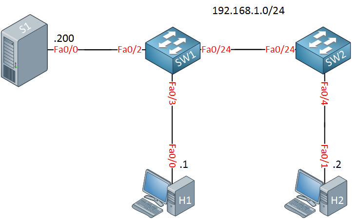
So what happens when there is no multicast router in the network? Let’s find out! We will use the exact same topology except the router is gone:

The switches don’t know of a router port now.
Let’s configure the two hosts to leave and rejoin our multicast group:
H1(config)#interface FastEthernet 0/0
H1(config-if)#no ip igmp join-group 239.1.1.1
H1(config-if)#ip igmp join-group 239.1.1.1H2(config)#interface FastEthernet 0/1
H2(config-if)#no ip igmp join-group 239.1.1.1
H2(config-if)#ip igmp join-group 239.1.1.1Here’s what you will see in the debug:
SW1#
IGMPSN: group: Received IGMPv2 report for group 239.1.1.1 received on Vlan 1, port Fa0/3
IGMPSN: No mroute detected: Drop IGMPv2 report for group 239.1.1.1 received on Vlan 1, port Fa0/3
SW2#
IGMPSN: group: Received IGMPv2 report for group 239.1.1.1 received on Vlan 1, port Fa0/4
IGMPSN: No mroute detected: Drop IGMPv2 report for group 239.1.1.1 received on Vlan 1, port Fa0/4This is rather harsh…the switches don’t know any multicast routers so they decide to drop the membership reports from the hosts.
What does this mean? Let’s try another ping:
S1#ping 239.1.1.1 repeat 1000
Type escape sequence to abort.
Sending 1000, 100-byte ICMP Echos to 239.1.1.1, timeout is 2 seconds:

Reply to request 0 from 192.168.1.2, 4 ms
Reply to request 0 from 192.168.1.1, 4 ms
Our pings are still working. The problem here is that the switches are flooding all multicast traffic now, treating it like broadcast traffic.
Solutions
How do we solve this issue?


Thanks , great learning again.
If you have to tell just theoretically- what exactly is the role of multicast-router in first example. what would that be ? because in our earlier examples video server was behind router but in our first example its behind the switch. my concept will get clear with this.
Hi Abhishek,
The role of the multicast router is that it “polls” (general queries) if there are any receivers still interested in receiving multicast traffic for certain groups. Receivers will always respond to this.
IGMP snooping requires this “poll and replying” to work correctly. Otherwise it will be unable to learn all receivers in the network. By default, the router will send these general queries. If there is no router, we can also configure the switch to send these general queries (as demonstrated in this lesson).
Rene
Understood well now. Thankyou Rene.
Hi Rene; this is nice. Will setup lab for this. Meanwhile, Quick question: unless specifically configured, with redundant routers, multicasting querier highest or lowest IP? Can you confirm?
Hi Parajuli,
The multicast querier is the router with the lowest IP address. This can be confusing sometimes as the PIM designated router is the one with the HIGHEST IP address.
Rene