Lesson Contents
Cisco IOS routers support two types of shaping:
- shape average
- shape peak
In my first lesson I explained the basics of shaping and I demonstrated how to configure shape average. This time we will take a look at peak shaping which is often misunderstood and confusing for many networking students.
Shape Average
Here’s a quick recap of how shape average works:
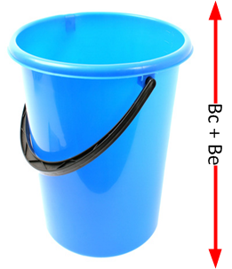
We have a bucket, and it can contain Bc and Be tokens. At the beginning of the Tc, because the token bucket is now larger, we can “save” tokens up to the Be level. The advantage of having a bigger bucket is that we can save tokens when we have periods of time where we send fewer bits than the configured shaping rate.
After a period of inactivity, we can send our Bc and Be tokens, allowing us to burst for a short time. When we use a bucket that has Bc and Be, this is what our traffic pattern will look like:
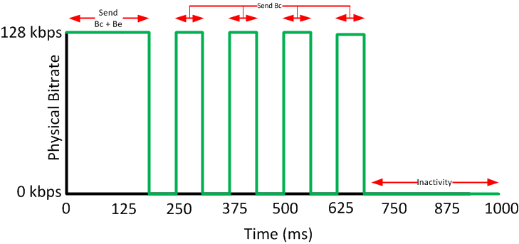
Above you can see that we start with a period where we are able to spend Bc and Be tokens, the next interval only the Bc tokens are renewed so we are only able to spend those. After awhile a period of inactivity allows us to fill our bucket again.
Shape Peak
Peak shaping uses the Be in a completely different way. We still have a token bucket that stores Bc + Be but will fill our token bucket with Bc and Be tokens each Tc and unused tokens will be discarded.
Here’s what our traffic pattern will look like:
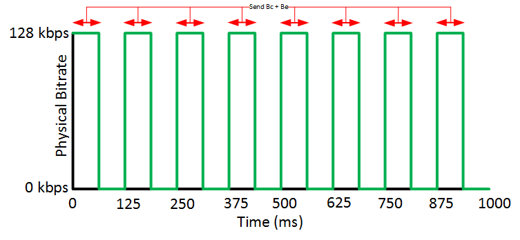
Each Tc our Bc and Be tokens are renewed so we are able to spend them. A period of inactivity doesn’t mean anything.
Now you might be wondering why do we use this and what’s the point of it?
Depending on your traffic contract, an ISP might give you a CIR and PIR (Peak Information Rate). The rate is the guaranteed bandwidth that they offer you, the PIR is the maximum non-guaranteed rate that you could get when there is no congestion on the network. When there is congestion, this traffic might be dropped. ISPs typically use policing to enforce these traffic contracts.
The idea behind peak shaping is that we can configure shaping and take the CIR and PIR of the ISP into account.
When we send a lot of traffic, we will be spending the Bc and Be tokens each Tc and we are shaping up to the PIR. When there isn’t as much traffic to shape, we only spend Bc tokens and that’s when we are shaping up to the CIR.
Let’s look at an configuration example which will help to clarify things.
Configuration
I will use the following topology to demonstrate peak shaping:
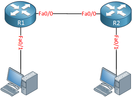
Above we have two computers and two routers. The computers will be used to generate traffic with iPerf, I’ll configure peak shaping on R1. Let’s do a quick test with iPerf, time to start the server:
Great explanation my friend. Thank you for making this tutorial very clear and concise.
Kyle
In the paragraph at the end, just wondering where you got the 1024 from for the sustained bits per interval?
Hello Chris,
If you configure
shape averageand configure only the shaping rate then you get a Bc and Be:R1(config-pmap-c)#shape average 256000This shows:
So I only reconfigured it and set the Be to 0:
R1(config-pmap-c)#shape average 256000 1024 0And we get:
Hello Rene/Laz,
I have a few questions and I am going to use the below topology as the reference.
https://cdn-forum.networklessons.com/uploads/default/original/2X/5/557c9567785977e39a8d57eb4a93324326547066.png
In this topology, there are two internet connections as you see in the picture and HSRP is configured between them. One router is active for one VLAN and another router is active for another VLAN is HSRP. There are two different firewalls for two different purposes. In this scenario, a lot of packet discards are being observed in the Trust zone and Untru
... Continue reading in our forumI just found out that GLBP will not help for load balancing in this case since only firewall will be ARPing to the GLBP Virtual IP. Therefore, we can take GLBP out of the picture. Instead, an equal cost static route will be effective. Thanks.
Azm