Lesson Contents
In a previous lesson I explained how we can use shaping to enforce lower bitrates. In this lesson, I will explain how to configure shaping. This is the topology we will use:
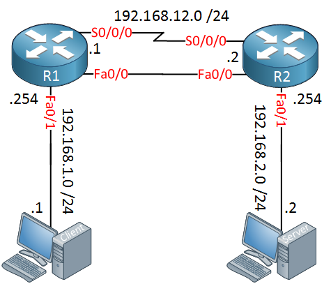
Above we have two routers connected to each other with a serial and FastEthernet link. We’ll use both interfaces to play with shaping. The computers are used for iPerf which is a great application to test the maximum achievable bandwidth. The computer on the left side is our client, on the right side we have the server. Right now we are using the serial interfaces thanks to the following static routes:
R1#
ip route 192.168.2.0 255.255.255.0 192.168.12.2
R2#
ip route 192.168.1.0 255.255.255.0 192.168.12.1Let’s take a look at some examples!
Configuration
We will start with some low bandwidth settings. Let’s set the clock rate of the serial interface to 128 Kbps:
R2(config)#interface Serial 0/0/0
R2(config-if)#clock rate 128000
Let’s start iPerf on the server:
SERVER# iperf -s
------------------------------------------------------------
Server listening on TCP port 5001
TCP window size: 85.3 KByte (default)
------------------------------------------------------------
That’s all we have to do on the server side, it will listen on the default port with a window size of 85.3 Kbyte. Here’s what we will do on the client side:
CLIENT# iperf -c 192.168.2.2 -P 8
------------------------------------------------------------
Client connecting to 192.168.2.2, TCP port 5001
TCP window size: 85.0 KByte (default)
------------------------------------------------------------
[  4] local 192.168.1.1 port 44344 connected with 192.168.2.2 port 5001
[  5] local 192.168.1.1 port 44345 connected with 192.168.2.2 port 5001
[  6] local 192.168.1.1 port 44346 connected with 192.168.2.2 port 5001
[  7] local 192.168.1.1 port 44347 connected with 192.168.2.2 port 5001
[  8] local 192.168.1.1 port 44348 connected with 192.168.2.2 port 5001
[  3] local 192.168.1.1 port 44343 connected with 192.168.2.2 port 5001
[  9] local 192.168.1.1 port 44349 connected with 192.168.2.2 port 5001
[ 10] local 192.168.1.1 port 44350 connected with 192.168.2.2 port 5001
The “-P” parameter tells the client to establish eight connections. I’m using multiple connections so we get a nice average bandwidth. Here’s what you will see on the server:
Server#
[ ID] Interval       Transfer     Bandwidth
[  4]  0.0-136.2 sec   256 KBytes  15.4 Kbits/sec
[ 10]  0.0-137.0 sec   256 KBytes  15.3 Kbits/sec
[ 11]  0.0-138.0 sec   256 KBytes  15.2 Kbits/sec
[  9]  0.0-138.4 sec   256 KBytes  15.1 Kbits/sec
[  5]  0.0-148.0 sec   384 KBytes  21.3 Kbits/sec
[  6]  0.0-166.7 sec   384 KBytes  18.9 Kbits/sec
[  8]  0.0-171.4 sec   384 KBytes  18.4 Kbits/sec
[  7]  0.0-172.9 sec   384 KBytes  18.2 Kbits/sec
[SUM]  0.0-172.9 sec  2.50 MBytes   121 Kbits/sec
Above you see the individual connections and the [SUM] is the combined throughput of all connections. 121 Kbps comes pretty close to the clock rate of 128 Kbps which we configured.
Let’s configure shaping to limit the throughput of Iperf. This is done with the MQC (Modular Quality of Service) framework which makes the configuration very simple. First we need to configure an access-list which matches our traffic:
R1(config)#ip access-list extended IPERF_CLIENT_SERVER
R1(config-ext-nacl)#permit ip host 192.168.1.1 host 192.168.2.2
The access-list above will match all traffic from 192.168.1.1 to 192.168.2.2. Now we need to create a class-map:
R1(config)#class-map IPERF
R1(config-cmap)#match access-group name IPERF_CLIENT_SERVER
The class map is called IPERF and matches our access-list. Now we can configure a policy-map:
R1(config)#policy-map SHAPE_AVERAGE
R1(config-pmap)#class IPERF
R1(config-pmap-c)#shape ?
  adaptive        Enable Traffic Shaping adaptation to BECN
  average         configure token bucket: CIR (bps) [Bc (bits) [Be (bits)]],
                  send out Bc only per interval
  fecn-adapt      Enable Traffic Shaping reflection of FECN as BECN
  fr-voice-adapt  Enable rate adjustment depending on voice presence
  peak            configure token bucket: CIR (bps) [Bc (bits) [Be (bits)]],
                  send out Bc+Be per interval
In the policy-map we select the class-map, above you can see the options for shaping. We’ll start with a simple example:
R1(config-pmap-c)#shape average ?
  <8000-154400000>  Target Bit Rate (bits/sec). (postfix k, m, g optional;
                    decimal point allowed)
  percent           % of interface bandwidth for Committed information rate
We will go for shape average where we have to specify the target bit rate. Let’s go for 64 Kbps (64000 bps):
R1(config-pmap-c)#shape average 64000 ?
  <32-154400000>  bits per interval, sustained. Recommend not to configure, the
                  algorithm will fi
When you configure the target bit rate, there’s an option to specify the bits per interval. Cisco IOS recommends you not to configure this manually so for now, we’ll stick to configuring the bit rate. This means Cisco IOS will automatically calculate the Bc and Tc:
R1(config-pmap-c)#shape average 64000That’s all there is to it. Now we can activate our policy-map on the interface:
R1(config)#interface Serial 0/0/0
R1(config-if)#service-policy output SHAPE_AVERAGE
Everything is now in place, let’s try iPerf again:
CLIENT# iperf -c 192.168.2.2 -P 8Here’s the sum on the server:
SERVER#
[SUM]  0.0-300.5 sec  2.12 MBytes  59.3 Kbits/sec
Great, that’s close to 64 Kbps. Here’s what it looks like on our router:
R1#show policy-map interface Serial 0/0/0
 Serial0/0/0

  Service-policy output: SHAPE_AVERAGE

    Class-map: IPERF (match-all)
      1916 packets, 2815928 bytes
      5 minute offered rate 41000 bps, drop rate 0 bps
      Match: access-group name IPERF_CLIENT_SERVER
      Queueing
      queue limit 64 packets
      (queue depth/total drops/no-buffer drops) 0/324/0
      (pkts output/bytes output) 1592/2330664
      shape (average) cir 64000, bc 256, be 256
      target shape rate 64000

    Class-map: class-default (match-any)
      102 packets, 7456 bytes
      5 minute offered rate 0 bps, drop rate 0 bps
      Match: any

      queue limit 64 packets
      (queue depth/total drops/no-buffer drops) 0/0/0
      (pkts output/bytes output) 47/3319
Above you can see that we have matched packets on our policy-map. Cisco IOS decided to use 256 bits for the Bc value.
How did it come up with this value? The Tc can be calculated like this:
Tc = Bc / CIRThis is what the formula looks like:
256 / 64000 = 0.004.
By using a Bc value of 256 bits, our Tc becomes 4 ms.
Let’s look at some more examples, I’ll also explain how to change the Be and Tc values.
this is what im waiting for! thanks! will read this!
Been waiting for this! thank you..
Thanks Rene!
This is exactly what i needed to better understand this.
Also nice to know that newer ios versions adopt the Tc value as 4ms now, i.s.o 125ms before.
That makes it good for all in regards to voice and video or latency sensitive traffic!
Hi Edwin,
That’s good to hear! I agree that 125 ms was a bit too much. Decreasing the Tc could increase the CPU load, I haven’t really tested this but it might be something to keep in mind…next time I’m messing around with shaping I’ll see what the impact is
Rene
I work with Carrier Ethernet circuits that have policed Committed Burst Size variables. If I understand this correctly, I should be to shape the traffic using shape average (CIR) (CBSx8) (EBS) x 8. According to MEF, a good rule of thumb for CBS is 8x mtu. We typically have an EBS of 0. Would it be appropriate to divide the CBS by two use that value for CBS and EBS or is another strategy more better?