In this lesson, I will show you how to configure VLANs on Cisco Catalyst Switches and how to assign interfaces to certain VLANs. Let’s start with a simple network topology:
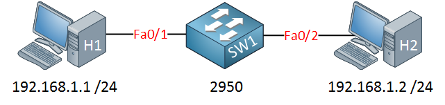
Let’s start with a simple example. H1 and H2 are connected to SW1.
First, we will look at the default VLAN configuration on SW1:
SW1#show vlan

VLAN Name                             Status    Ports
---- -------------------------------- --------- -------------------------------
1    default                          active    Fa0/1, Fa0/2, Fa0/3, Fa0/4
                                                Fa0/5, Fa0/6, Fa0/7, Fa0/8
                                                Fa0/9, Fa0/10, Fa0/12
                                                Fa0/13, Fa0/14, Fa0/22
                                                Fa0/23, Fa0/24, Gi0/1, Gi0/2
1002 fddi-default                     act/unsup
1003 token-ring-default               act/unsup
1004 fddinet-default                  act/unsup
1005 trnet-default                    act/unsup
Interesting…VLAN 1 is the default LAN and you can see that all active interfaces are assigned to VLAN 1.
VLAN information is not saved in the running-config or startup-config but in a separate file called vlan.dat on your flash memory. If you want to delete the VLAN information, you should delete this file by typing delete flash:vlan.dat. I configured an IP address on H1 and H2 so they are in the same subnet.
Let’s see if H1 and H2 can reach each other:
C:\Documents and Settings\H1>ping 192.168.1.2

Pinging 192.168.1.2 with 32 bytes of data:

Reply from 192.168.1.2: bytes=32 time<1ms TTL=128
Reply from 192.168.1.2: bytes=32 time<1ms TTL=128
Reply from 192.168.1.2: bytes=32 time<1ms TTL=128
Reply from 192.168.1.2: bytes=32 time<1ms TTL=128

Ping statistics for 192.168.1.2:
Packets: Sent = 4, Received = 4, Lost = 0 (0% loss),
Approximate round trip times in milli-seconds:
Minimum = 0ms, Maximum = 0ms, Average = 0ms
Even with the default switch configuration, H1 can reach H2. Let’s see if I can create a new VLAN for H1 and H2:
SW1(config)#vlan 50
SW1(config-vlan)#name Computers
SW1(config-vlan)#exit
This is how you create a new VLAN. If you want, you can give it a name, but this is optional. I’m calling my VLAN “Computers.”
SW1#show vlan

VLAN Name                             Status    Ports
---- -------------------------------- --------- -------------------------------

1    default                          active    Fa0/1, Fa0/2, Fa0/3, Fa0/4
                                                Fa0/5, Fa0/6, Fa0/7, Fa0/8
                                                Fa0/9, Fa0/10, Fa0/11, Fa0/12
                                                Fa0/13, Fa0/14, Fa0/15,
                                                Fa0/23, Fa0/24, Gi0/1, Gi0/2
50   Computers                        active
VLAN 50 was created on SW1, and you can see that it’s active. However, no ports are currently in VLAN 50. Let’s see if we can change this…
SW1(config)interface fa0/1
SW1(config-if)#switchport mode access
SW1(config-if)#switchport access vlan 50

SW1(config)interface fa0/2
SW1(config-if)#switchport mode access
SW1(config-if)#switchport access vlan 50
First, I will configure the switchport in access mode with the switchport mode access command. By using the switchport access vlan command, we can move our interfaces to another VLAN.
SW1#show vlan

VLAN Name                             Status    Ports
---- -------------------------------- --------- -------------------------------

1    default                          active    Fa0/3, Fa0/4
                                                Fa0/5, Fa0/6, Fa0/7, Fa0/8
                                                Fa0/9, Fa0/10,, Fa0/12
                                                Fa0/13, Fa0/14, Fa0/15,
                                                Fa0/23, Fa0/24, Gi0/2

50   Computers                        active    Fa0/1, Fa0/2
Excellent! Both computers are now in VLAN 50. Let’s verify our configuration by checking if they can ping each other:
C:\Documents and Settings\H1>ping 192.168.1.2

Pinging 192.168.1.2 with 32 bytes of data:
Reply from 192.168.1.2: bytes=32 time<1ms TTL=128
Reply from 192.168.1.2: bytes=32 time<1ms TTL=128
Reply from 192.168.1.2: bytes=32 time<1ms TTL=128
Reply from 192.168.1.2: bytes=32 time<1ms TTL=128

Ping statistics for 192.168.1.2:
Packets: Sent = 4, Received = 4, Lost = 0 (0% loss),
Approximate round trip times in milli-seconds:
Minimum = 0ms, Maximum = 0ms, Average = 0ms
Our computers can reach each other within VLAN 50. Besides pinging each other, we can also use another show command to verify our configuration:
SW1#show interfaces fa0/1 switchport
Name: Fa0/1
Switchport: Enabled
Administrative Mode: static access
Operational Mode: static access
Administrative Trunking Encapsulation: negotiate
Operational Trunking Encapsulation: native
Negotiation of Trunking: Off
Access Mode VLAN: 50 (Computers)
Trunking Native Mode VLAN: 1 (default)
SW1#show interfaces fa0/2 switchport
Name: Fa0/2
Switchport: Enabled
Administrative Mode: static access
Operational Mode: static access
Administrative Trunking Encapsulation: negotiate
Operational Trunking Encapsulation: native
Negotiation of Trunking: Off
Access Mode VLAN: 50 (Computers)
Trunking Native Mode VLAN: 1 (default)
By using the show interfaces switchport command, we can see that the operational mode is “static access,” which means it’s in access mode. We can also verify that the interface is assigned to VLAN 50.
Configurations
Want to take a look for yourself? Here you will find the final configuration of the switch.
tnx
thanks! easy to understand well explained
Thanks..
Very neatly explained. Thanks.
Hi Rene, I installed cisco packet tracer and execute vlan lab and everything looks good so far. What is GNS3vault and is it downloadable for free?
Thanks,
Maruti.