Since you are reading this I assume you understand how “classic” spanning tree works. If you don’t, it’s best to read my Introduction to spanning tree first before you continue.
Having said that, let’s start with a nice picture:
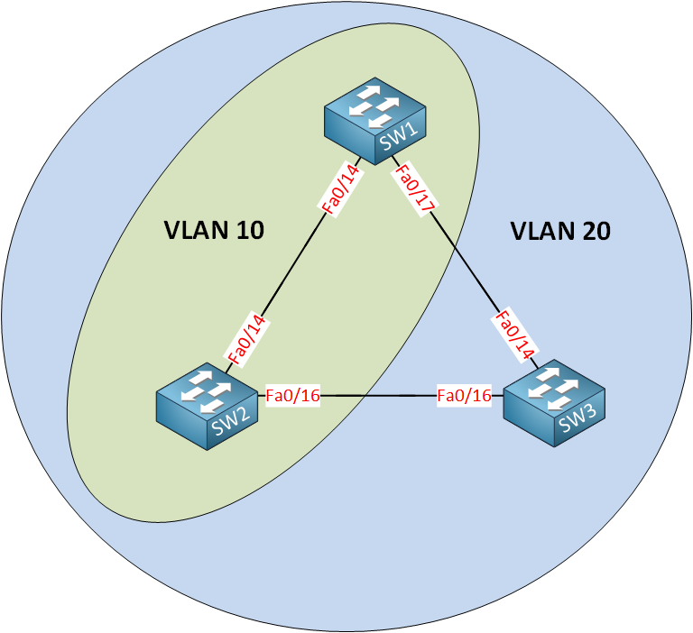
- VLAN 10 is configured on SW1 and SW2.
- VLAN 20 is configured on SW1, SW2 and SW3.
Question for you: do we have a loop in VLAN 10? What about VLAN 20?
There’s a big difference between our physical and logical topology. We don’t have a loop in VLAN 10 because it only runs on the link between SW1 and SW2. We DO have a loop within VLAN 20, however.
How does spanning tree deal with this? Simple…we’ll calculate a different spanning tree for each VLAN! The oldest version of spanning tree is called CST (Common Spanning Tree) and is defined in the 802.1D standard. It only calculates a single spanning tree for all VLANs.
Another version of spanning tree is able to calculate a topology for each VLAN. This version is called PVST (Per VLAN Spanning Tree), and it’s the default on Cisco switches.
Let’s look at an example of three switches and two VLANs. Both VLANs are available on all switches:
Rene, you overviews are really good and easy to understand, on the above example there is no fa0/16 on switch A. Unless I’m not seeing right. Thanks
Hi Shaj,
Thanks! I just fixed it, it should be Fa0/17.
Rene
Hi rene , have u got any lessons on RSTP ??
M Q
Hi Muhammed,
For sure, here they are:
https://networklessons.com/spanning-tree/rapid-spanning-tree-rstp
https://networklessons.com/spanning-tree/rapid-spanning-tree-configuration
Rene
Hi Rene, how do you configure PVSTP?
Could you give me an example?