Tunneling is a concept where we put ‘packets into packets’ so they can be transported over certain networks. We also call this encapsulation.
A good example is when you have two sites with IPv6 addresses on their LAN, but they are only connected to the Internet with IPv4 addresses. Normally it would be impossible for the two IPv6 LANs to reach each other, but by using tunneling, the two routers will put IPv6 packets into IPv4 packets so that our IPv6 traffic can be routed on the Internet.
Another example is where we have an HQ and a branch site, and you want to run a routing protocol like RIP, OSPF, or EIGRP between them. We can tunnel these routing protocols so that the HQ and branch router can exchange routing information.
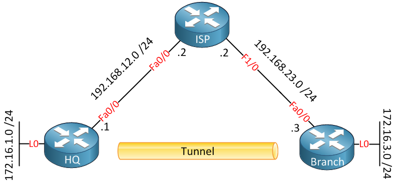
Basically, when you configure a tunnel, it’s like you create a point-to-point connection between the two devices. GRE (Generic Routing Encapsulation) is a simple tunneling technique that can do this for us. Let me show you a topology that we will use to demonstrate GRE:

Above, we have three routers connected to each other. On the left side, we have the “HQ” router, our headquarters. On the right side, there is a “Branch” router that is supposed to be a branch office. Both routers are connected to the Internet. In the middle, on top, there is an ISP router. We can use this topology to simulate two routers connected to the Internet. The HQ and Branch router each have a loopback interface representing the LAN.
Let me show you the basic configuration of these routers so that you can recreate it if you want:
HQ(config)#interface fastEthernet 0/0
HQ(config-if)#ip address 192.168.12.1 255.255.255.0
HQ(config-if)#exit
HQ(config)#interface loopback0
HQ(config-if)#ip address 172.16.1.1 255.255.255.0
HQ(config-if)#exit
HQ(config)#ip route 192.168.23.3 255.255.255.255 192.168.12.2ISP(config)#interface fastEthernet 0/0
ISP(config-if)#ip address 192.168.12.2 255.255.255.0
ISP(config-if)#exit
ISP(config)#interface fastEthernet 1/0
ISP(config-if)#ip address 192.168.23.2 255.255.255.0Branch(config)#interface fastEthernet 0/0
Branch(config-if)#ip address 192.168.23.3 255.255.255.0
Branch(config-if)#exit
Branch(config)#interface loopback 0
Branch(config-if)#ip address 172.16.3.3 255.255.255.0
Branch(config-if)#exit
Branch(config)#ip route 192.168.12.1 255.255.255.255 192.168.23.2I created a static route on the HQ and Branch routers so that they can reach each other through the ISP router. They will be unable to reach the networks on each other’s loopback interfaces, however. Now let’s create a tunnel:
HQ(config)#interface tunnel 1
HQ(config-if)#tunnel source fastEthernet 0/0
HQ(config-if)#tunnel destination 192.168.23.3
HQ(config-if)#ip address 192.168.13.1 255.255.255.0Branch(config)#interface tunnel 1
Branch(config-if)#tunnel source fastEthernet 0/0
Branch(config-if)#tunnel destination 192.168.12.1
Branch(config-if)#ip address 192.168.13.3 255.255.255.0You can pick any number for the tunnel interface that you like. We need to specify a source and destination IP address to build the tunnel, and we’ll use the 192.168.13.0 /24 subnet on the tunnel interface. Let’s verify that our tunnel is working:
HQ#show interfaces tunnel 1
Tunnel1 is up, line protocol is up
  Hardware is Tunnel
  Internet address is 192.168.13.1/24
  MTU 1514 bytes, BW 9 Kbit, DLY 500000 usec,
     reliability 255/255, txload 1/255, rxload 1/255
  Encapsulation TUNNEL, loopback not set
  Keepalive not set
  Tunnel source 192.168.12.1 (FastEthernet0/0), destination 192.168.23.3
Tunnel protocol/transport GRE/IPBranch#show interfaces tunnel 1
Tunnel1 is up, line protocol is up
Hardware is Tunnel
Internet address is 192.168.13.3/24
MTU 1514 bytes, BW 9 Kbit, DLY 500000 usec,
reliability 255/255, txload 1/255, rxload 1/255
Encapsulation TUNNEL, loopback not set
Keepalive not set
Tunnel source 192.168.23.3 (FastEthernet0/0), destination 192.168.12.1
Tunnel protocol/transport GRE/IPAbove, you can see that the tunnel interface is up/up on both routers. The default tunneling mode is GRE. Let’s see if both routers can reach each other:
Branch#ping 192.168.13.1

Type escape sequence to abort.
Sending 5, 100-byte ICMP Echos to 192.168.13.1, timeout is 2 seconds:
!!!!!
Success rate is 100 percent (5/5), round-trip min/avg/max = 4/7/12 ms
There we go…they can ping each other without any issues! So that wasn’t too bad, right? Let’s see if we can enable a routing protocol so that we can advertise the loopback interfaces. I’ll use EIGRP for this:
HQ(config)#router eigrp 13
HQ(config-router)#no auto-summary
HQ(config-router)#network 192.168.13.0
HQ(config-router)#network 172.16.1.0Branch(config)#router eigrp 13
Branch(config-router)#no auto-summary
Branch(config-router)#network 192.168.13.0
Branch(config-router)#network 172.16.3.0I’ll activate EIGRP on the tunnel and loopback interfaces. You will see that both routers establish an EIGRP neighbor adjacency through the tunnel interface. Let’s check the routing tables:


Good stuff Rene.
Next steps would be configuration for VRF-lite aware GRE tunnel with IPsec?
https://cdn-forum.networklessons.com/images/emoji/apple/slight_smile.png?v=14
That would be a good idea. I’ll write something soon.
Thank you, very helpful!
i am going to read more from this website!
Excellent ! I am new to Tunnelling stuff. Helped me to understand well. Thanks Rene
Glad I could help Satish.