Lesson Contents
In the previous lesson we discussed the basics of multicast routing and I explained some of the differences between dense and sparse mode multicast routing protocols. The only multicast routing protocol that is fully supported on Cisco IOS devices is PIM (Protocol Independent Multicast).
The independent part is a bit confusing…PIM depends 100% on the information in the unicast routing table but it doesn’t matter which unicast routing protocol you use to fill it. Other multicast routing protocols like DVMRP and MOSPF don’t use the unicast routing table but build their own tables.
PIM supports three different modes:
- PIM Dense mode
- PIM Sparse mode
- PIM Sparse-Dense mode
Here’s the key difference between sparse and dense mode:
- Dense mode: we forward multicast traffic on all interfaces until a downstream router requests us to stop fowarding.
- Sparse mode: we don’t forward multicast traffic on any interface until a downstream router requests us to forward it.
In this lesson, we’ll take a close look at PIM dense mode.
PIM dense mode is a push method where we use source based trees. What does this mean? Let’s look at an example:
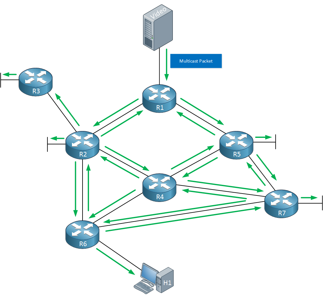
Above we see a video server sending a multicast packet towards R1. As soon as R1 receives this multicast packet it will create an entry in its multicast routing table where it stores the source address and multicast group address. It will then flood the traffic on all of its interfaces.
Other routers that receive this multicast packet will do the same thing, the multicast packet is flooded on all of their interfaces. This does cause some issues, one problem is that we will have multicast routing loops. For example you can see that the packet that R1 receives is forwarded to R2 > R4 > R5 and back to R1 (and the other way around). How do we deal with this? Take a look below:
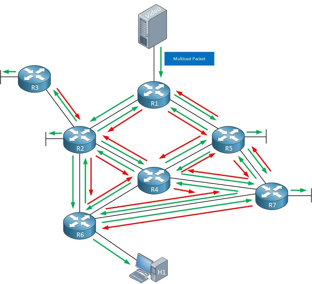
Each router that is not interested in the multicast traffic will send a prune to its upstream router, requesting it to stop forwarding it. The upstream router is the router where we receive multicast traffic from, a downstream router is a router where we forward multicast traffic to. The red arrows above are the prune messages that the routers will send. There are a couple of reasons why a router can send a prune message:
- When we don’t have any directly connected hosts that are interested in receiving the multicast traffic.
- When no downstream routers are interested in receiving the multicast traffic.
- When we receive traffic on a non-RPF interface.
RPF (Reverse Path Forwarding) is an additional check that helps to prevent multicast routing loops:
When a router receives a multicast packet it will check the source IP address of this packet in the unicast routing table. It will check the next hop and outgoing interface that we use to reach the source.
- When the multicast packet was received on the interface that we use to reach the source, the RPF check succeeds.
- When the multicast packet was received on another interface, it fails the RPF check and the packet is discarded.
The end result will look like this:
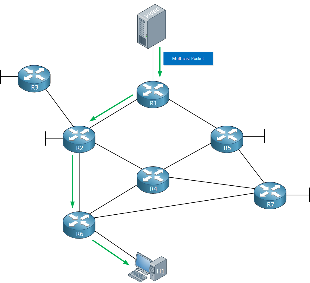
We now have a nice clean topology where multicast traffic is flooded from R1 to R2 > R6 > H1. This flood and prune behavior will occur every three minutes.
We call this topology the source-based distribution tree or SPT (Shortest Path Tree). Sometimes it’s also called the source tree:
- The tree defines the path from the source to the receiver(s).
- The source is the root of our tree.
- The routers in between that are forwarding traffic are the nodes.
- The subnets with receivers are the branches and leaves of the tree.
Depending on the source and/or multicast groups that we use, you might have more than one source tree in your network. Once we look at the configuration, you’ll see that we use the [S,G] notation to refer to a particular source tree:
- S: the source address
- G: the multicast group address.
Now you have an idea what PIM dense mode is about, let’s see what it looks like on some real routers shall we?
Configuration
We will use the following topology for this demonstration:
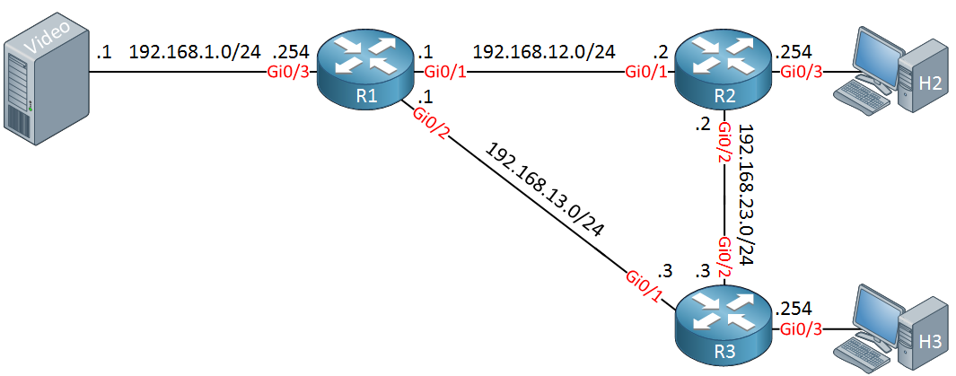
Above we have a video server on the left side which will be the source of our multicast traffic. H2 and H3 are two host devices who want to receive the multicast traffic. R1, R2 and R3 will be configured to use PIM dense mode.
Unicast Routing
First we will configure a routing protocol on all routers, I’ll pick OSPF. All interfaces will be advertised:
R1(config)#router ospf 1
R1(config-router)#network 192.168.1.0 0.0.0.255 area 0
R1(config-router)#network 192.168.12.0 0.0.0.255 area 0
R1(config-router)#network 192.168.13.0 0.0.0.255 area 0R2(config)#router ospf 1
R2(config-router)#network 192.168.2.0 0.0.0.255 area 0
R2(config-router)#network 192.168.12.0 0.0.0.255 area 0
R2(config-router)#network 192.168.23.0 0.0.0.255 area 0R3(config)#router ospf 1
R3(config-router)#network 192.168.3.0 0.0.0.255 area 0
R3(config-router)#network 192.168.13.0 0.0.0.255 area 0
R3(config-router)#network 192.168.23.0 0.0.0.255 area 0Now we can focus on the multicast configuration.
PIM Dense Mode
Multicast routing is disabled by default on Cisco IOS routers so we have to enable it:
R1, R2 & R3
(config)#ip multicast-routing
Now we can configure PIM. Let’s start with R1:
R1(config)#interface GigabitEthernet 0/1
R1(config-if)#ip pim dense-mode
As soon as I enable PIM dense mode on the interface our router will start sending PIM hello packets. Here’s what these look like in wireshark:
Frame 1: 72 bytes on wire (576 bits), 72 bytes captured (576 bits) on interface 0
Ethernet II, Src: fa:16:3e:18:8b:e1 (fa:16:3e:18:8b:e1), Dst: IPv4mcast_0d (01:00:5e:00:00:0d)
Internet Protocol Version 4, Src: 192.168.12.1, Dst: 224.0.0.13
Protocol Independent Multicast
    0010 .... = Version: 2
    .... 0000 = Type: Hello (0)
    Reserved byte(s): 00
    Checksum: 0x174b [correct]
    PIM Options: 5
        Option 1: Hold Time
            Holdtime: 1
        Option 20: Generation ID: 847877769
            Type: 20
            Length: 4
            Generation ID: 847877769
        Option 19: DR Priority: 1
            Type: 19
            Length: 4
            DR Priority: 1
        Option 21: State Refresh Capable: Version = 1, Interval = 0s
            Type: 21
            Length: 4
            Version: 1
            Interval: 0
            Reserved: 0
        Option 65004: Unknown: 65004
            Type: 65004
            Length: 0
Above you can see the type of the packet (hello) and it also shows the hold time. For whatever reason, wireshark (version 2.0.1) is showing me a value of 1 but the default is 105 seconds. If you want to take a look at this packet yourself, here’s the packet capture:
Packet Capture: Multicast PIM Dense Mode Hello Packet
It shows the correct holdtime of 105 seconds.
Let’s enable PIM dense on R2 as well:
R2(config)#interface GigabitEthernet 0/1
R2(config-if)#ip pim dense-mode
As soon as we do this, R1 and R2 will become neighbors since they receive each others PIM hello packets.If they keep receiving them before the holddown timer is expired then they will keep seeing each other as PIM neighbors.:
R1#
%PIM-5-NBRCHG: neighbor 192.168.12.2 UP on interface GigabitEthernet0/1
Let’s enable all the other interfaces. You also need to enable PIM on interfaces that connect to host devices:
R1(config)#interface GigabitEthernet 0/2
R1(config-if)#ip pim dense-mode

R1(config)#interface GigabitEthernet 0/3
R1(config-if)#ip pim dense-modeR2(config)#interface GigabitEthernet 0/2
R2(config-if)#ip pim dense-mode
R2(config)#interface GigabitEthernet 0/3
R2(config-if)#ip pim dense-modeR3(config)#interface GigabitEthernet 0/1
R3(config-if)#ip pim dense-mode
R3(config)#interface GigabitEthernet 0/2
R3(config-if)#ip pim dense-mode
R3(config)#interface GigabitEthernet 0/3
R3(config-if)#ip pim dense-modePIM Dense Neighbors
Let’s make sure all routers have become neighbors:
R1#show ip pim neighbor
PIM Neighbor Table
Mode: B - Bidir Capable, DR - Designated Router, N - Default DR Priority,
      P - Proxy Capable, S - State Refresh Capable, G - GenID Capable,
      L - DR Load-balancing Capable
Neighbor          Interface                Uptime/Expires    Ver   DR
Address                                                            Prio/Mode
192.168.12.2      GigabitEthernet0/1       00:05:59/00:01:37 v2    1 / DR S P G
192.168.13.3 GigabitEthernet0/2 00:00:48/00:01:26 v2 1 / DR S P GR2#show ip pim neighbor
PIM Neighbor Table
Mode: B - Bidir Capable, DR - Designated Router, N - Default DR Priority,
P - Proxy Capable, S - State Refresh Capable, G - GenID Capable,
L - DR Load-balancing Capable
Neighbor Interface Uptime/Expires Ver DR
Address Prio/Mode
192.168.12.1 GigabitEthernet0/1 00:06:18/00:01:22 v2 1 / S P G
192.168.23.3 GigabitEthernet0/2 00:01:00/00:01:43 v2 1 / DR S P GR3#show ip pim neighbor
PIM Neighbor Table
Mode: B - Bidir Capable, DR - Designated Router, N - Default DR Priority,
P - Proxy Capable, S - State Refresh Capable, G - GenID Capable,
L - DR Load-balancing Capable
Neighbor Interface Uptime/Expires Ver DR
Address Prio/Mode
192.168.13.1 GigabitEthernet0/1 00:01:14/00:01:29 v2 1 / S P G
192.168.23.2 GigabitEthernet0/2 00:01:09/00:01:33 v2 1 / S P GAbove we can see that all routers have become PIM neighbors. The default version on Cisco IOS is version 2. The expiry times is the holddown timer that is counting down. Each time when the router receives a PIM hello packet, it will reset itself to 00:01:45 (105 seconds).
Multicast Routing
Let’s take a look at the multicast routing tables:
R1#show ip mroute
IP Multicast Routing Table
Flags: D - Dense, S - Sparse, B - Bidir Group, s - SSM Group, C - Connected,
       L - Local, P - Pruned, R - RP-bit set, F - Register flag,
       T - SPT-bit set, J - Join SPT, M - MSDP created entry, E - Extranet,
       X - Proxy Join Timer Running, A - Candidate for MSDP Advertisement,
       U - URD, I - Received Source Specific Host Report,
       Z - Multicast Tunnel, z - MDT-data group sender,
       Y - Joined MDT-data group, y - Sending to MDT-data group,
       G - Received BGP C-Mroute, g - Sent BGP C-Mroute,
       N - Received BGP Shared-Tree Prune, n - BGP C-Mroute suppressed,
       Q - Received BGP S-A Route, q - Sent BGP S-A Route,
       V - RD & Vector, v - Vector, p - PIM Joins on route,
       x - VxLAN group
Outgoing interface flags: H - Hardware switched, A - Assert winner, p - PIM Join
 Timers: Uptime/Expires
 Interface state: Interface, Next-Hop or VCD, State/Mode

(*, 224.0.1.40), 00:12:12/00:02:48, RP 0.0.0.0, flags: DCL
  Incoming interface: Null, RPF nbr 0.0.0.0
  Outgoing interface list:
    GigabitEthernet0/2, Forward/Dense, 00:03:06/stopped
GigabitEthernet0/1, Forward/Dense, 00:12:12/stoppedR2#show ip mroute
IP Multicast Routing Table
Flags: D - Dense, S - Sparse, B - Bidir Group, s - SSM Group, C - Connected,
L - Local, P - Pruned, R - RP-bit set, F - Register flag,
T - SPT-bit set, J - Join SPT, M - MSDP created entry, E - Extranet,
X - Proxy Join Timer Running, A - Candidate for MSDP Advertisement,
U - URD, I - Received Source Specific Host Report,
Z - Multicast Tunnel, z - MDT-data group sender,
Y - Joined MDT-data group, y - Sending to MDT-data group,
G - Received BGP C-Mroute, g - Sent BGP C-Mroute,
N - Received BGP Shared-Tree Prune, n - BGP C-Mroute suppressed,
Q - Received BGP S-A Route, q - Sent BGP S-A Route,
V - RD & Vector, v - Vector, p - PIM Joins on route,
x - VxLAN group
Outgoing interface flags: H - Hardware switched, A - Assert winner, p - PIM Join
Timers: Uptime/Expires
Interface state: Interface, Next-Hop or VCD, State/Mode
(*, 224.0.1.40), 00:08:33/00:02:35, RP 0.0.0.0, flags: DCL
Incoming interface: Null, RPF nbr 0.0.0.0
Outgoing interface list:
GigabitEthernet0/2, Forward/Dense, 00:03:15/stopped
GigabitEthernet0/1, Forward/Dense, 00:08:33/stoppedR3#show ip mroute
IP Multicast Routing Table
Flags: D - Dense, S - Sparse, B - Bidir Group, s - SSM Group, C - Connected,
L - Local, P - Pruned, R - RP-bit set, F - Register flag,
T - SPT-bit set, J - Join SPT, M - MSDP created entry, E - Extranet,
X - Proxy Join Timer Running, A - Candidate for MSDP Advertisement,
U - URD, I - Received Source Specific Host Report,
Z - Multicast Tunnel, z - MDT-data group sender,
Y - Joined MDT-data group, y - Sending to MDT-data group,
G - Received BGP C-Mroute, g - Sent BGP C-Mroute,
N - Received BGP Shared-Tree Prune, n - BGP C-Mroute suppressed,
Q - Received BGP S-A Route, q - Sent BGP S-A Route,
V - RD & Vector, v - Vector, p - PIM Joins on route,
x - VxLAN group
Outgoing interface flags: H - Hardware switched, A - Assert winner, p - PIM Join
Timers: Uptime/Expires
Interface state: Interface, Next-Hop or VCD, State/Mode
(*, 224.0.1.40), 00:03:24/00:02:10, RP 0.0.0.0, flags: DCL
Incoming interface: Null, RPF nbr 0.0.0.0
Outgoing interface list:
GigabitEthernet0/2, Forward/Dense, 00:03:20/stopped
GigabitEthernet0/1, Forward/Dense, 00:03:24/stoppedAt this moment we don’t have any multicast traffic going on but we do see a multicast group in the tables, 224.0.1.40. This can be confusing if you are new to multicast, let me explain:
PIM sparse mode (which we will discuss in other lessons) uses a RP (Rendezvous Point) and Cisco routers support a protocol called “Auto RP Discovery” to automatically find the RP in the network. Auto RP uses this multicast group address, 224.0.1.40.
PIM dense mode doesn’t use RPs so there is no reason at all for our routers to listen to the 224.0.1.40 group address. For whatever reason, as soon as you enable PIM then autoRP is also enabled and the router will listen to this group address. You can ignore this entry completely when you are working with PIM dense mode.
If you take a close look then you can see that none of the routers are receiving or forwarding traffic for this group:
- The incoming interface is null.
- The outgoing interface list shows stopped.
Let’s generate some multicast traffic ourselves. First i’ll have to configure one of the hosts to join a multicast group. Let’s configure H2 to join 239.1.1.1:
H2(config)#interface GigabitEthernet 0/1
H2(config-if)#ip igmp join-group 239.1.1.1
Let’s check how this influences the multicast routing table of R2:
R2#show ip mroute 239.1.1.1

(*, 239.1.1.1), 00:00:19/00:02:51, RP 0.0.0.0, flags: DC
  Incoming interface: Null, RPF nbr 0.0.0.0
  Outgoing interface list:
    GigabitEthernet0/3, Forward/Dense, 00:00:19/stopped
    GigabitEthernet0/2, Forward/Dense, 00:00:19/stopped
    GigabitEthernet0/1, Forward/Dense, 00:00:19/stopped
Above we can see that R2 has created an *, 239.1.1.1 entry for multicast group 239.1.1.1. At this moment however we are not receiving any traffic for this group so we don’t know what the source is and we can’t forward anything.
Let’s change that. The most simple method to generate multicast traffic is to send a ping from the multicast group address:
S1#ping 239.1.1.1 repeat 2147483647
Type escape sequence to abort.
Sending 2147483647, 100-byte ICMP Echos to 239.1.1.1, timeout is 2 seconds:

Reply to request 0 from 192.168.2.2, 132 ms
Reply to request 1 from 192.168.2.2, 7 ms
Reply to request 2 from 192.168.2.2, 6 ms
Above you can see that H2 is replying. Let’s check the multicast routing tables:
R1#show ip mroute 239.1.1.1

IP Multicast Routing Table
Flags: D - Dense, S - Sparse, B - Bidir Group, s - SSM Group, C - Connected,
       L - Local, P - Pruned, R - RP-bit set, F - Register flag,
       T - SPT-bit set, J - Join SPT, M - MSDP created entry, E - Extranet,
       X - Proxy Join Timer Running, A - Candidate for MSDP Advertisement,
       U - URD, I - Received Source Specific Host Report,
       Z - Multicast Tunnel, z - MDT-data group sender,
       Y - Joined MDT-data group, y - Sending to MDT-data group,
       G - Received BGP C-Mroute, g - Sent BGP C-Mroute,
       N - Received BGP Shared-Tree Prune, n - BGP C-Mroute suppressed,
       Q - Received BGP S-A Route, q - Sent BGP S-A Route,
       V - RD & Vector, v - Vector, p - PIM Joins on route,
       x - VxLAN group
Outgoing interface flags: H - Hardware switched, A - Assert winner, p - PIM Join
 Timers: Uptime/Expires
 Interface state: Interface, Next-Hop or VCD, State/Mode

(*, 239.1.1.1), 00:01:16/stopped, RP 0.0.0.0, flags: D
  Incoming interface: Null, RPF nbr 0.0.0.0
  Outgoing interface list:
    GigabitEthernet0/2, Forward/Dense, 00:01:16/stopped
    GigabitEthernet0/1, Forward/Dense, 00:01:16/stopped

(192.168.1.1, 239.1.1.1), 00:01:16/00:01:43, flags: T
  Incoming interface: GigabitEthernet0/3, RPF nbr 0.0.0.0
  Outgoing interface list:
    GigabitEthernet0/1, Forward/Dense, 00:01:16/stopped
    GigabitEthernet0/2, Prune/Dense, 00:01:15/00:01:43
Let’s discuss what we see above:
- R1 is receiving multicast traffic for 239.1.1.1 from 192.168.1.1 on its Gi0/3 interface and has added this entry in its multicast routing table. This is the [S,G] entry that I explained before.
- R1 has been forwarding this traffic for one minute and 16 seconds on the Gi0/1 interface.
- If R1 does not receive any multicast packets from 192.168.1.1 for one minute and 43 seconds, the (S,G) entry will expire and be removed. As long as we keep receiving packets, this timer will be reset to three minutes.
- The T flags means that we are using the shortest path source tree.
- The RPF neighbor for R1 is 0.0.0.0, this value is empty since it’s a directly connected interface.
- R1 is forwarding traffic on its Gi0/1 interface that is connected to R2. It has been doing this for one minute and 16 seconds and there is no expiry. It will keep doing this until it gets pruned.
- R1 has stopped forwarding traffic on its Gi0/2 interface since it is pruned.
Since R3 is not interested in receiving this multicast traffic and it has sent a prune message to R1, asking it to stop forwarding this traffic. Here’s what this prune message looks like:
Frame 1: 68 bytes on wire (544 bits), 68 bytes captured (544 bits) on interface 0
Ethernet II, Src: fa:16:3e:a4:e8:90 (fa:16:3e:a4:e8:90), Dst: IPv4mcast_0d (01:00:5e:00:00:0d)
Internet Protocol Version 4, Src: 192.168.13.3, Dst: 224.0.0.13
Protocol Independent Multicast
    0010 .... = Version: 2
    .... 0011 = Type: Join/Prune (3)
    Reserved byte(s): 00
    Checksum: 0x5995 [correct]
    PIM Options
        Upstream-neighbor: 192.168.13.1
        Reserved byte(s): 00
        Num Groups: 1
        Holdtime: 210
        Group 0: 239.1.1.1/32
            Num Joins: 0
            Num Prunes: 1
                IP address: 192.168.1.1/32
Above you can see that this packet was sent by R3 (192.168.13.3) and destined to 224.0.0.13 (PIM version 2).
PIM uses a single packet for join and prune messages, in this packet we can see that R3 requests a prune for 239.1.1.1 from 192.168.1.1. This packet is meant for 192.168.13.1.
Depending on your IOS version, it is possible that state refresh is disabled by default. You can enable it with the ip pim state-refresh origination-interval command.
An interface is pruned for three minutes and each time we send a prune message, this timer will be resetted. If we stop sending prune messages then the interface will go back into forwarding after three minutes.
Want to see this packet for yourself? Take a look here:
Packet Capture: Multicast PIM Dense Mode Prune Packet
Let’s check R2:
R2#show ip mroute 239.1.1.1

(*, 239.1.1.1), 00:03:47/stopped, RP 0.0.0.0, flags: DC
  Incoming interface: Null, RPF nbr 0.0.0.0
  Outgoing interface list:
    GigabitEthernet0/3, Forward/Dense, 00:03:47/stopped
    GigabitEthernet0/2, Forward/Dense, 00:03:47/stopped
    GigabitEthernet0/1, Forward/Dense, 00:03:47/stopped

(192.168.1.1, 239.1.1.1), 00:01:22/00:01:37, flags: T
  Incoming interface: GigabitEthernet0/1, RPF nbr 192.168.12.1
  Outgoing interface list:
    GigabitEthernet0/2, Prune/Dense, 00:01:22/00:01:37
    GigabitEthernet0/3, Forward/Dense, 00:01:22/stopped
Let’s discuss what we have above:
- R2 has set the DC flags for this group. The D means we are using dense mode and the C means that we have a directly connected host that wants to receive this traffic (H2).
- R2 has been receiving traffic from 192.168.1.1 to 239.1.1.1 on its Gi0/1 interface. The RPF neighbor is 192.168.12.1 (R1).
- R2 has stopped forwarding traffic on its Gi0/2 interface towards R3.
- R2 is forwarding traffic on its Gi0/3 interface towards H2.
What about R3?
R3#show ip mroute 239.1.1.1

(*, 239.1.1.1), 00:01:27/stopped, RP 0.0.0.0, flags: D
  Incoming interface: Null, RPF nbr 0.0.0.0
  Outgoing interface list:
    GigabitEthernet0/2, Forward/Dense, 00:01:27/stopped
    GigabitEthernet0/1, Forward/Dense, 00:01:27/stopped

(192.168.1.1, 239.1.1.1), 00:01:27/00:01:32, flags: PT
  Incoming interface: GigabitEthernet0/1, RPF nbr 192.168.13.1
  Outgoing interface list:
    GigabitEthernet0/2, Prune/Dense, 00:01:27/00:01:32, A
Let’s see:
- R3 is receiving traffic for 239.1.1.1 from 192.168.1.1 on its Gi0/1 interface that connects to R1. The RPF neighbor is 192.168.13.1.
- The P flag means that this traffic has been pruned.
- R3 has pruned its Gi0/2 interface. The A flag stands for assert winner.
So the big question…what is an assert winner?
R2 and R3 are both connected to the 192.168.23.0/24 subnet and both of them are receiving traffic from R1.
Let’s imagine that we have a host on the 192.168.23.0/24 subnet that wants to receive multicast traffic. Which router will forward this traffic? R2 or R3? If both routers forward multicast traffic then the host would receive duplicate multicast packets.
Hello Rene,
The explanation under the r1#show ip mroute 239.1.1.1:
“R1 has been receiving this traffic for one minute and 16 seconds.” I think R1 has been sending the information out gi0/1
"R1 is forwarding traffic on its Gi0/1 interface that is connected to R1. " I think there is a typo, R1 is connected on its gi0/1 to R2
Hi Jose,
That’s correct, I just fixed this. Thanks for letting me know!
Rene
Hi,
What ios you are using for H1 ,H2 and routers ?
Thanks
Hi Sims,
I believe I used Cisco VIRL for this with the latest IOSv image:
Rene
Just to let you know, if your image is a layer 3 device, then for the config to work as Rene has put it, with default-gateway, you need to “no ip routing”.
Otherwise, just do a default route.
Usually the method used in the lab is for Layer 2 devices.