Lesson Contents
Our own networks are called LANs (Local Area Network). We own and operate these networks. It’s called a “local” area network since all devices that make up the LAN are close to each other. Perhaps in one building or a few buildings close to each other (called a campus).
When we need access to other remote networks, connect two LANs together or give others access to our LAN, we need a WAN (Wide Area Network). As the name implies, WANs cover large geographical areas. This could be a network between two cities or as large as the Internet.
WANs are operated by companies like phone/cable companies, service providers, or satellite companies. They build large networks that span entire cities or regions and lease the right to use their networks to their customers.
On the LAN, the dominant protocol that we use is Ethernet. For wide area networks, there are dozens of technologies and protocols we can choose from. Most WAN technologies describe layer one and two of the OSI model:
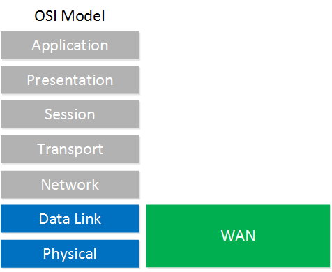
On the physical layer, we use different hardware, cables, connectors and interfaces. On the data link layer, there are a number of different WAN protocols that we can use. We’ll discuss these.
Physical Layer Terminology
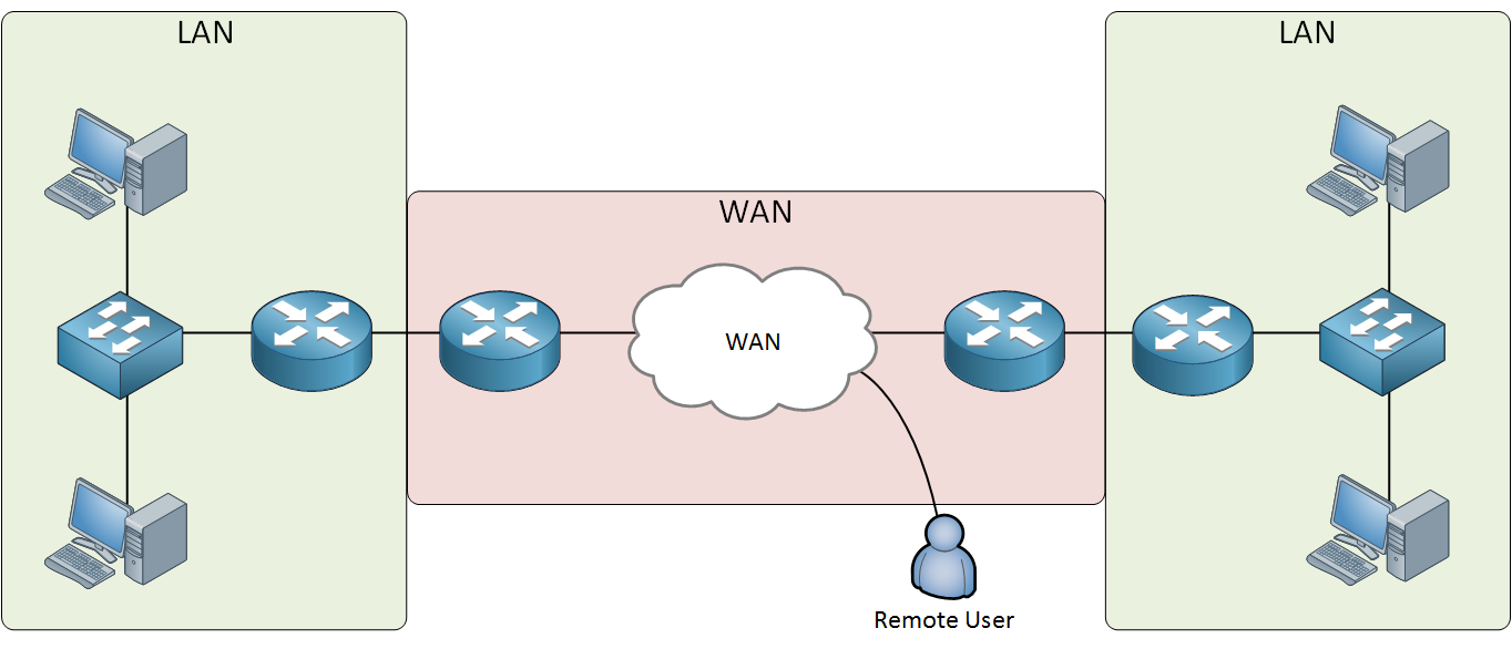
When you read about WAN technologies and protocols, there is a lot of terminology you might encounter. Let’s look at a picture:

The picture above is what a WAN solution in general looks like. Let me walk you through the different items in the picture:
- On the left side in the green box, we have the customer network that is paying for the services of the WAN service provider.
- On the right side, in the blue box, we have the WAN service provider with its hardware.
- The CPE (Customer Premises Equipment) are all devices, wiring, and hardware that are located at the site of the customer. These devices are connected to the WAN of the WAN service provider. The CPE might be owned by the customer or leased from the service provider. A combination is also possible. Perhaps the router is owned by the customer and the modem is leased from the service provider.
- All hardware and devices that belong to the service provider is called the service provider equipment.
- The demarcation point (demarc) is where the service provider’s wiring ends and where the customer’s wiring begins. Depending on which country you live in, this could be a so-called meter box/meter cupboard inside or outside your house or building.
- The DTE (Data Terminal Equipment) is the customer device that forwards data from the customer’s network to the WAN. This can be a router, computer or sometimes a switch.
- The CSU/DSU (Channel Service Unit / Data Service Unit) is a device that sits in between the router and WAN connection. It converts digital signals from the WAN into a digital signal the router understands and vice versa. For example, the CSU/DSU might be connected to the router with a DTE serial cable, so it has to speak a language the router understands. On the other side, the CSU/DSU is connected to a two pair cable to the WAN service provider which speaks another language. Back in the days, the CSU/DSU was a separate device. Nowadays this is integrated in router interfaces.
- The DCE (Data Circuit-terminating Equipment) is the device that receives data from the DTE, modulates into an analog signal and forwards it onto the wire to the service provider. It also demodulates analog signals that it receives on the wire into digital signals. This device is a modem and nowadays often integrated in interfaces or routers.
- The local loop is the physical link that connects from the demarcation point at the customer to the edge of the service provider network. It’s also often called the “last mile”.
- The CO (Central Office) is the building where all lines from local loops to the customers end up. In this building, we will find CO switches where the lines terminate. The kind of CO switch used depends on the technology that is used (telephony, DSL, cable, etc.).
WAN Technologies
There are a number of different methods how we can forward data on a network:
- Circuit switching
- Packet switching
- Cell switching
Let me explain these and show you some examples.
Circuit Switching
To understand circuit switching, it’s best to look at how telephony worked back in the 60s:
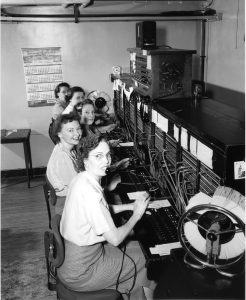
The phone network used telephone switchboards that were operated by switchboard operators who connected calls by plugging in phone plugs in the required phone jacks. To connect long distance calls, operators had to work together with operators in other offices.
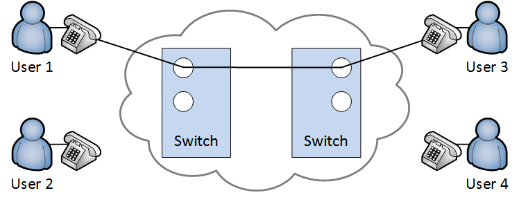
Once the correct plugs were connected, a circuit was established between two callers which allowed them to talk to each other. Here’s a visualization:
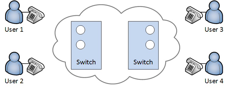
Above we have four users, the cloud is the phone network with two switchboards. Let’s say user 1 and user 3 would like to talk to each other. The operators would plug in the required phone plugs to establish a circuit like this:
The circuit that is established is used exclusively by user 1 and user 3. It doesn’t matter if they talk a lot or enjoy each other’s silence, nobody else can use this circuit. User 2 and user 4 would also like to talk to each other. After connecting the right phone plugs, the circuit is established:

We now have two circuits and the network is at 100% capacity. It doesn’t matter how much “data” our users are generating by talking or not. What if we had a fifth user?
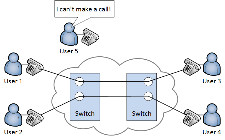
The fifth user has to wait since there is no available capacity in our network. We will have to wait until one of the calls is completed so the circuit can be disconnected.
Later, the operators were replaced by electromechanical automatic telephone exchanges but circuit switching was still used to establish analog phone calls on our PSTN (Public Switched Telephone Network) which is also known as POTS (Post Office Telephone Service or Plain Old Telephone System).
ISDN (Integrated Services Digital Network) also used circuit switching and supported data rates of 64 kbps per data channel.
The example above explains the limitations of circuit switching. Once the circuit is established, the capacity is reserved for that circuit.
The problem with circuit switching is the limited capacity that it offers. Once the circuit is established, you make a reservation in the network and you end up with a fixed capacity for the circuit. It doesn’t matter how much data you transmit or not, the circuit will be there for you. This also means that you waste a lot of unused resources…
Packet Switching
The idea behind it is that we break our data down in “chunks”. Each chunk is a packet that is sent on the network. This is what we mostly use on our networks nowadays. Here’s a visualization:
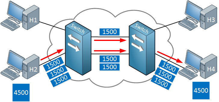
Above you can see that host 2 wants to send 4500 bytes of data. This is broken down in 3x 1500 byte packets. One packet is sent on the top link, the other two on the bottom link. With packet switching, there’s no fixed path in the network. Once host 4 receives all packets, it can extract and reassemble the data.
The packet size is variable, there is no fixed size.
Packet switching has mostly replaced circuit switching. One of the advantages is that because there are no fixed circuits, we can more effectively use the capacity that the network has to offer. We don’t waste any unused resources.
Cell Switching
Cell switching is very similar to packet switching with the exception that we use a fixed for our size for our cells. Here’s an example:
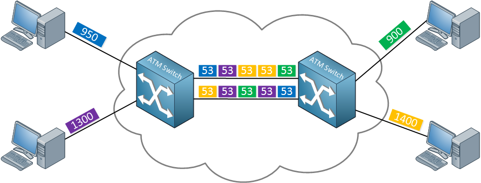
Above you can see that each computer sends some data. Whatever they send gets encapsulated in cells with a fixed size, 53 bytes in my example. ATM (Asynchronous Transfer Mode) was a popular WAN protocol that used cell switching.
WAN Technology
So far, we talked about some physical layer terminology and different methods to forward data on a network. Let’s look now at some actual WAN technologies that we use or used in the past.
Leased Lines
Leased lines are one of the older WAN options. Imagine we have a LAN in New York and another LAN in Miami. Somehow, we need to connect these two networks. A leased line is a point-to-point link that we exclusively use, often offered by a phone company. Leased lines have been out there for awhile so there are a bunch of other names we use for this:
- T1 / T3 / E1 / E3
- Point-to-point link
- Serial link
- Leased circuit
This point to point link will only be used by the customer that is paying for it, which makes it an expensive option. From the customer’s perspective, it looks like this:
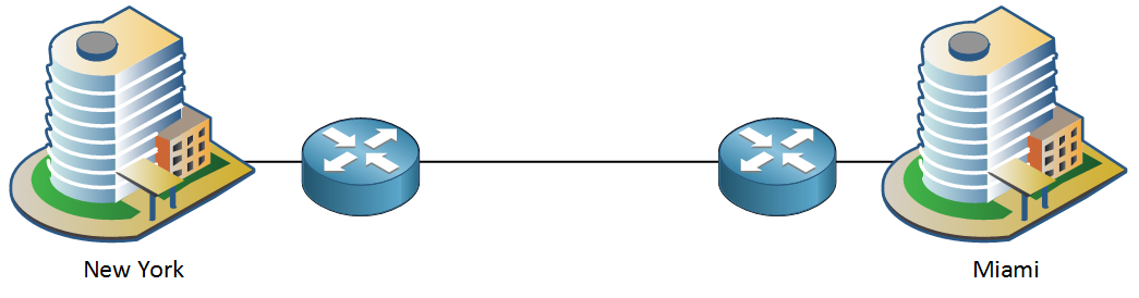
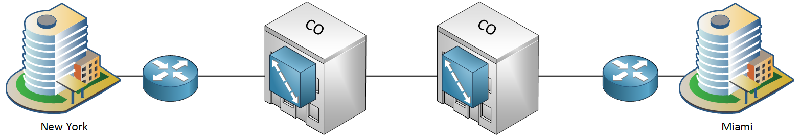
On each site, we use a router with the point-to-point connection in between. In reality, there is no single connection that spans the ~1300 miles between New York and Miami. The phone company has multiple buildings throughout the country with their equipment, called COs (Central Office). These COs are connected to most buildings in a city, hoping that they can sell their services some day. When a customer requires a leased line, the phone company creates a connection between COs to build a point-to-point link:
There are a number of different bandwidth options for leased lines. Here are some examples:
| Type | Speed | Region |
| DS0 | 64 Kbps | USA |
| T1 (DS1) | 1.54 Mbps | USA |
| T3 (DS3) | 43.736 Mbps | USA |
| E0 | 64 Kbps | Europe |
| E1 | 2.048 Mbps | Europe |
| E3 | 34.368 Mbps | Europe |
In the USA, we have DS (Digital Signal) 1, 2 and 3. The DS1 option are 24 multiplexed DS0 lines, called T1. The DS3 line are 28 multiplexed DS1 lines The E0, E1 and E3 lines are the European equivalents.
Let’s take a closer look what the connection of a leased line looks like:
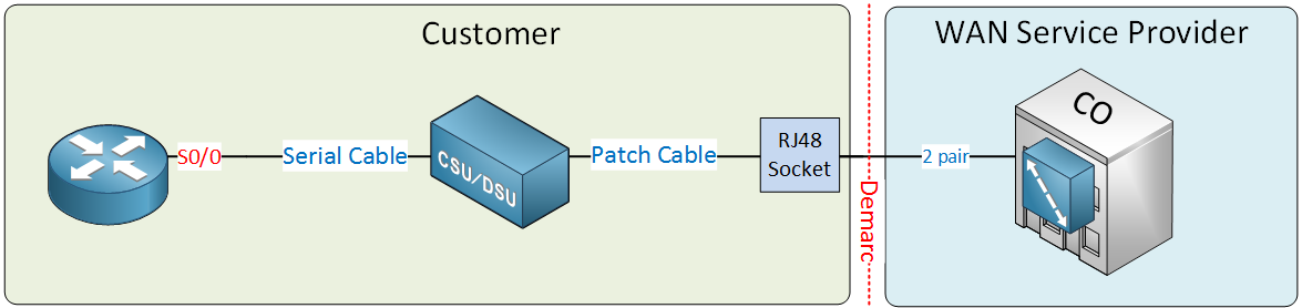
Above we see that the WAN service provider (phone company) offers a two pair cable to the customer, which terminates in an RJ48 socket. This socket is connected with a patch cable to the CSU/DSU. The CSU/DSU is connected to the router with a serial cable to a serial interface.
Let’s look at some pictures of these items/devices. Here’s a serial interface of a Cisco router:
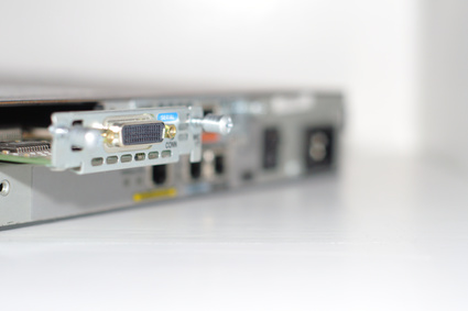
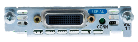
These serial interfaces are WIC modules that you can insert in some of the Cisco router models. Here’s an example of a CSU/DSU, the DC1200 by Metrodata:
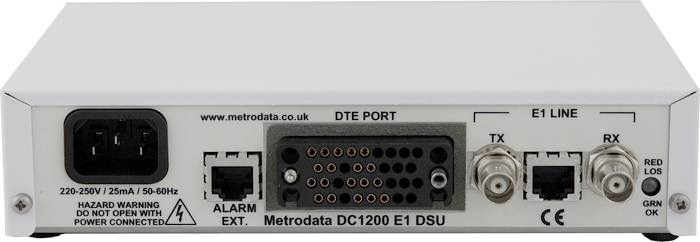
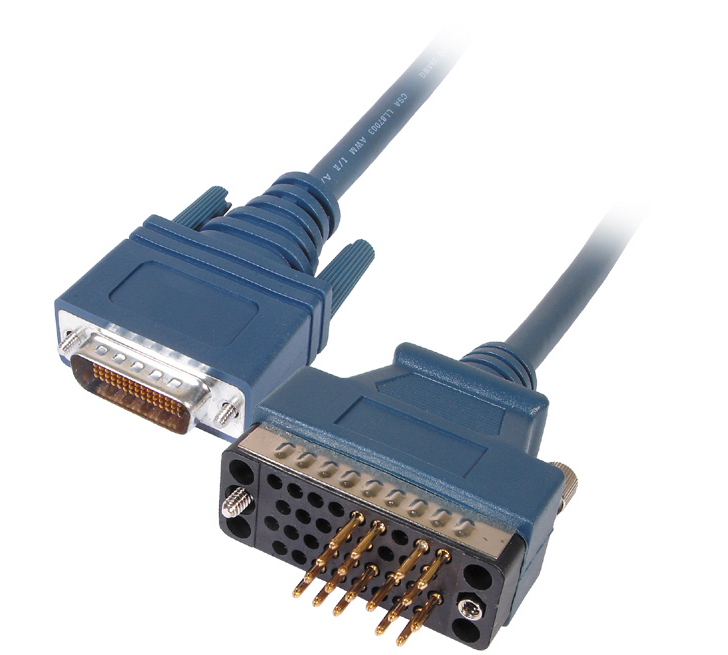
Above you can see DTE port that has to be connected to the router. On the right side there’s the connector for the E1 line. To connect the router to this device, we can use the following cable:
If you want to practice with leased lines in your own lab, then there is no need to buy a CSU/DSU. It is possible to connect two Cisco routers “back to back” with a serial cable:
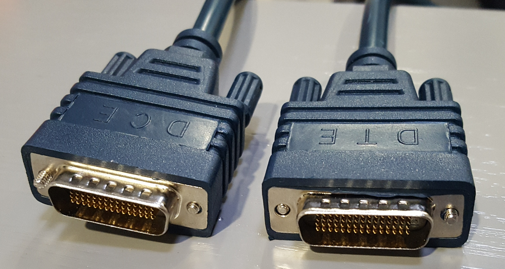
Above you can see that one connector is labeled as DCE, the other as DTE. To make a back to back serial link work, you will have to do one thing that normally the CSU/DSU does for you and that is clocking which defines the speed of the link. A Cisco router can configure clocking on the interface, which has to be done on the DCE interface.
On the data link layer, there are two protocols we can use on leased lines: PPP and HDLC
Frame-relay
Frame-relay is also an older WAN technology that was an alternative to leased lines. With a leased line, you are the only one using the link so it’s quite an expensive option. Frame-relay offers point-to-point and point-to-multipoint circuits with a shared network, which is cheaper than a dedicated line.
If you want to learn more about frame-relay, you can find our frame-relay course here.
DSL
DSL (Digital Subscriber Line) became a very popular option for high-speed Internet access since it uses the analog phone cables that pretty much every home or building has. The speed that you get depends on the distance between your home and the phone company.
Here’s what DSL looks like:
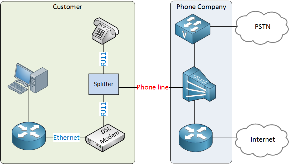
At the customer, we have a splitter that is connected to the phone line that the phone company offers. One RJ11 (phone cable) goes to your analog phones, the other one is connected to a DSL modem. The DSL modem has an Ethernet connection to your router. Nowadays, the DSL modem is often integrated in the router.
The phone company uses a device called a DSLAM (DSL access multiplexer) which splits the data traffic and voice traffic from each other. Data traffic is forwarded to a router, voice traffic to a voice switch.
Most DSL providers offer asymmetric speeds; the downstream bandwidth is higher than the upstream bandwidth. There are many flavors of DSL like ADSL, SDSL, HDSL and VDSL.
Cable
Cable Internet is similar to DSL, it also became popular since most homes and buildings have a cable connection. Cable Internet uses the DOCSIS (Data Over Cable Service Interface Specification) standard to transport data over a coaxial cable.
Coaxial cables offer a wider frequency range than the two pair phone cables we use for DSL, allowing higher throughput. Some cable providers offer ~ 300 Mbit connections.
Cable internet often offers higher bandwidth but this can depend on the number of subscribers on the network. Here’s an illustration:
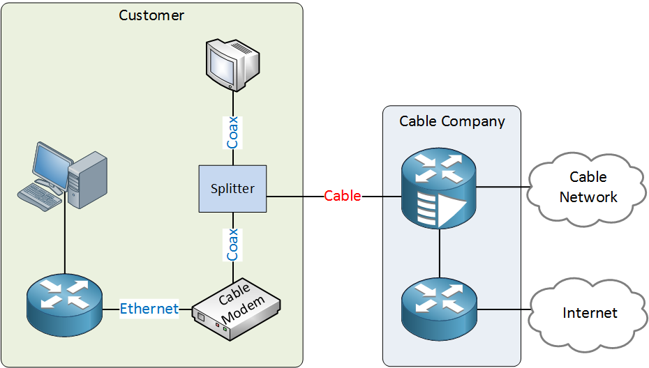
The picture above is similar to the DSL picture, except we now have coaxial cables and a cable modem. On the cable company side, we have to split the video and data traffic.
Ethernet
Ethernet has also made its way to the WAN. The 1000BASE-ZX standard, for example, supports a distance of ~40 miles over single-mode fiber connections. From the customer’s perspective, it looks similar to the leased line:
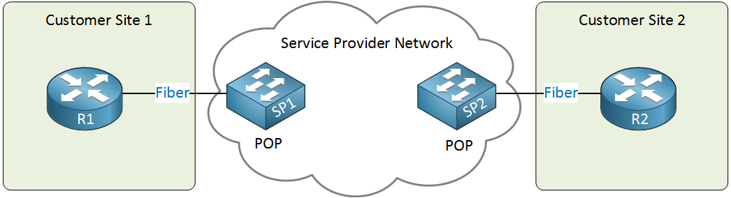
On each customer site, we have a router with a fiber connection to the Ethernet WAN provider. The connection at the service provider side is called the POP (Point of Presence). Many providers call this an Ethernet private line. It’s also possible to have more than two sites, creating a multi-access network.
Hello
For cell switching Data add to the cell have to be fix size and the same for all cell or can be different? like first cell 100 second cell 150.
Hi Heng,
The cell size is a fixed length, it doesn’t change.
Rene
Hi Rene,
If possible so please define and explain Circuit switching, I am confused.
Hello Muhammad
An excellent example of circuit switching can be found in the traditional telephony network. Until the mid 1980s, before digital telephone switches were in widespread use, telephony systems used mechanical switching. When you picked up the phone and dialed, telephone switches along the path between you and the party you called would whir into action and psychically connect wires and connectors in such a way that a physical circuit would be created between your phone and the called party’s phone. The following diagram illustrates this:
https://
... Continue reading in our forumThanks Lazaros, Nice explanation.