Lesson Contents
OSPF uses a DR (Designated Router) and BDR (Backup Designated Router) on each multi-access network to reduce routing update traffic and LSA flooding. If you have multiple routers on a multi-access segment, and all those routers would form neighbor adjacencies with each other, you would have a lot of unnecessary LSA flooding. The DR acts as a central point for the distribution of LSAs.
This election happens per multi-access segment, not per area. A multi-access network is a network segment with more than two routers where routers can reach each other directly. OSPF figures out whether a network is multi-access or not by looking at the interface type. For example, an Ethernet interface is considered multi-access, and a serial interface with PPP encapsulation is considered a point-to-point interface. OSPF automatically sets the correct OSPF network type for each interface.
Key Takeaways
- DR/BDR election occurs per multi-access segment, not per OSPF area
- Default OSPF priority is 1. The higher priority wins the election
- Setting priority to 0 prevents a router from becoming DR or BDR
- Election requires
clear ip ospf processcommand to take effect after priority changes - Point-to-point links (like serial interfaces) don’t use DR/BDR
- Routers that are neither DR nor BDR are called DROTHER
Configuration
Let’s look at this in action.
Multi-Access Network
We’ll start with an example of a multi-access network with a DR/BDR election. This is the topology we’ll use:
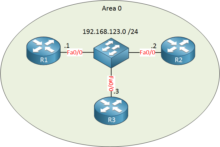
Here’s an example of a network with 3 OSPF routers on a FastEthernet network. They are connected to the same switch (multi-access network) so there will be a DR/BDR election. OSPF has been configured, so all routers have become OSPF neighbors. Let’s take a look:
R1#show ip ospf neighbor

Neighbor ID     Pri   State       Dead Time   Address       Interface
192.168.123.2   1   FULL/BDR      00:00:32    192.168.123.2 FastEthernet0/0
192.168.123.3   1   FULL/DR       00:00:31    192.168.123.3 FastEthernet0/0
From R1’s perspective, R2 is the BDR, and R3 is the DR.
R3#show ip ospf neighbor

Neighbor ID     Pri   State       Dead Time   Address         Interface
192.168.123.1   1   FULL/DROTHER  00:00:36    192.168.123.1 FastEthernet0/0
192.168.123.2   1   FULL/BDR      00:00:39    192.168.123.2 FastEthernet0/0
When a router is not the DR or BDR, it’s called a DROTHER. Here we can see that R1 is a DROTHER.
R2#show ip ospf neighbor

Neighbor ID     Pri   State       Dead Time   Address         Interface
192.168.123.1   1   FULL/DROTHER  00:00:31    192.168.123.1 FastEthernet0/0
192.168.123.3   1   FULL/DR       00:00:32    192.168.123.3 FastEthernet0/0
And R2 (the BDR) sees the DR and DROTHER.
Of course, we can change which router becomes the DR/BDR by playing with the priority. Let’s turn R1 in the DR:
R1(config)#interface fastEthernet 0/0
R1(config-if)#ip ospf priority 200
You change the priority if you like by using the ip ospf priority command:
- The default priority is 1.
- A priority of 0 means you will never be elected as DR or BDR.
- You need to use
clear ip ospf processbefore this change takes effect.
R1#show ip ospf neighbor

Neighbor ID     Pri   State       Dead Time   Address         Interface
192.168.123.2   1   FULL/BDR      00:00:31    192.168.123.2 FastEthernet0/0
192.168.123.3   1   FULL/DR       00:00:32    192.168.123.3 FastEthernet0/0
As you can see, R3 is still the DR, we need to reset the OSPF neighbor adjacencies so that we’ll elect the new DR and BDR.
R3#clear ip ospf process
Reset ALL OSPF processes? [no]: yesR2#clear ip ospf process
Reset ALL OSPF processes? [no]: yesI’ll reset all the OPSF neighbor adjacencies.
R1#show ip ospf neighbor

Neighbor ID     Pri   State       Dead Time   Address         Interface
192.168.123.2   1   FULL/DROTHER  00:00:36    192.168.123.2 FastEthernet0/0
192.168.123.3   1   FULL/BDR      00:00:30    192.168.123.3 FastEthernet0/0
Now you can see R1 is the DR because the other routers are DROTHER and BDR.
R3#show ip ospf neighbor
Neighbor ID     Pri  State        Dead Time   Address         Interface
192.168.123.1   200  FULL/DR      00:00:30    192.168.123.1 FastEthernet0/0
192.168.123.2   1    FULL/DROTHER 00:00:31    192.168.123.2 FastEthernet0/0
Or we can confirm it from R3. You’ll see that R1 is the DR and that the priority is 200.
Configurations
Want to take a look for yourself? Here you will find the startup configuration of each device.
R1
hostname R1
!
ip cef
!
interface FastEthernet0/0
 ip address 192.168.123.1 255.255.255.0
 ip ospf priority 200
!
router ospf 1
 network 192.168.123.0 0.0.0.255 area 0
!
end
R2
hostname R2
!
ip cef
!
interface FastEthernet0/0
 ip address 192.168.123.2 255.255.255.0
!
router ospf 1
 network 192.168.123.0 0.0.0.255 area 0
!
end
R3
hostname R3
!
ip cef
!
interface FastEthernet0/0
 ip address 192.168.123.3 255.255.255.0
!
router ospf 1
 network 192.168.123.0 0.0.0.255 area 0
!
end
Something you need to be aware of is that the DR/BDR election is per multi-access segment…not per area!). Let me give you an example:
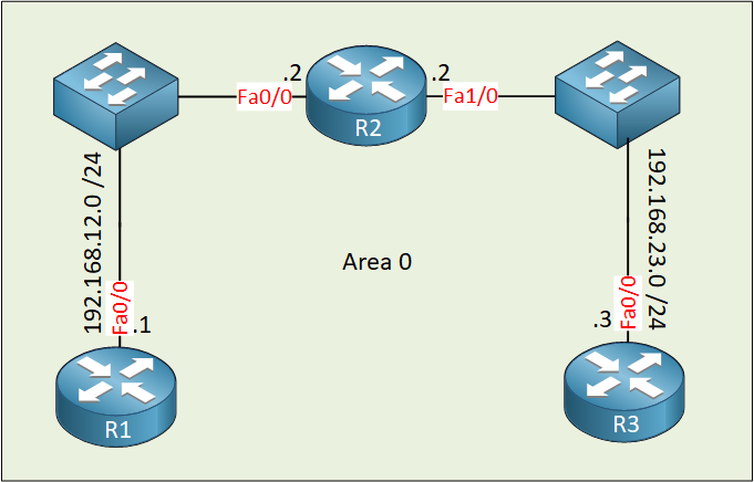
In the example above, we have two multi-access segments between R2 and R1, and between R2 and R3. For each segment, there will be a DR/BDR election.
Really helpful series of posts on OSPF. Thank you!
Thanks for this lesson, very helpful!
Wonderful explanation!! The best I’ve found on the web. CCNA books are not so clear!
Thanks!
Thanks Davide, glad to hear you like it!
simply awesome!!! Thanks a lot..