Lesson Contents
In the beginning, the development of networks was chaotic. Each vendor had its proprietary solution. The bad part was that one vendor’s solution was not compatible with another vendor’s solution. This is where the idea for the OSI model was born. Having a layered approach to networks, our hardware vendors would design hardware for the network, and others could develop software for the application layer. Using an open model which everyone agrees on means we can build networks that are compatible with each other.
To fix this problem, the International Organization for Standardization (ISO) researched different network models, and the result is the OSI-model which was released in 1984. Nowadays, most vendors build networks based on the OSI model, and hardware from different vendors is compatible….excellent!
The OSI model isn’t just a model to make networks compatible; it’s also one of the BEST ways to teach people about networks. Keep this in mind since when you are studying networking, you will see people refer a lot to the OSI model.
Here’s what the OSI model looks like:
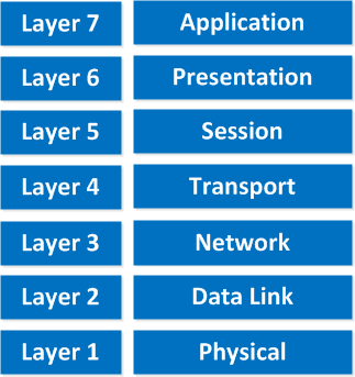
“All People Seem To Need Data Processing”
This is the OSI model, which has seven layers; we work our way from the bottom to the top. Let’s start at the physical layer:
- Physical Layer: This layer describes stuff like voltage levels, timing, physical data rates, physical connectors, and so on. Everything you can “touch” since it’s physical.
- Data Link: This layer makes sure data is formatted the correct way, takes care of error detection, and makes sure data is delivered reliably. This might sound a bit vague, but for now, remember that this is where “Ethernet” lives. MAC Addresses and Ethernet frames are on the Data Link layer.
- Network: This layer takes care of connectivity and path selection (routing). This is where IPv4 and IPv6 live. Every network device needs a unique address on the network.
- Transport: The transport layer takes care of transport. When you downloaded this lesson from the Internet, the webpage was sent in segments and transported to your computer.
- TCP lives here; it’s a protocol that sends data in a reliable way.
- UDP lives here; it’s a protocol that sends data in an unreliable way.
I’m taking a short break here, these four layers that I just described are important for networking, and the upper three layers are about applications.
- Session: The session layer takes care of establishing, managing, and terminating sessions between two hosts. When you are browsing a website on the internet, you are probably not the only user of the web server hosting that website. This web server needs to keep track of all the different “sessions.”
- Presentation: This one will make sure that information is readable for the application layer by formatting and structuring the data. Most computers use the ASCII table for characters. If another computer would use another character like EBCDIC, then the presentation layer needs to “reformat” the data, so both computers agree on the same characters.
- Application: Here are your applications. E-mail, browsing the web (HTTP), FTP, and many more.
“People Do Need To See Pamela Anderson”
This one normally gives me more smiles when I’m teaching CCNA in class, and it’s another way to remember the OSI-Model.
P = Physical
D = Data Link
N = Network
T = Transport
S = Session
P = Presentation
A = Application
Remember that you can’t skip any layers in the OSI model. It’s impossible to jump from the Application layer directly to the Network layer. You must always go through all the layers to send data over the network.
Let’s take a look at a real-life example of data transmission:
- You are sitting behind your computer and want to download some files from a local webserver. You start up your web browser and type in the URL of your favorite website. Your computer will send a message to the web server requesting a certain web page. You now use the HTTP protocol, which lives on the application layer.
- The presentation layer will structure the information of the application in a certain format.
- The session layer will make sure to separate all the different sessions.
- Depending on the application, you want a reliable (TCP) or unreliable (UDP) protocol to transfer data to the web server. In this case, it’ll choose TCP since you want to ensure the webpage makes it to your computer. We’ll discuss TCP and UDP later.
- Your computer has a unique IP address (for example, 192.168.1.1), and it will build an IP packet. This IP packet will contain all the data of the application, presentation, and session layer. It also specifies which transport protocol it’s using (TCP in this case) and the source IP address (your computer 192.168.1.1), and the destination (the web server’s IP address).
- The IP packet will be put into an Ethernet Frame. The Ethernet frame has a source MAC address (your computer) and the destination MAC address (webserver). More about Ethernet and MAC addresses later.
- Finally, everything is converted into bits and sent down the cable using electric signals.
Once again, you cannot “skip” any layers of the OSI model. You always have to work your way through ALL layers. If you want a real-life story converted to networking land, just think about the postal service:
- First, you write a letter.
- You put the letter in an envelope.
- You write your name and the name of the receiver on the envelope.
- You put the envelope in the mailbox.
- The content of the mailbox will go to the central processing office of the postal service.
- Your envelope will be delivered to the receiver.
- They open the envelope and read its contents.
If you put your letter directly in the mailbox, it won’t be delivered. Unless someone at the postal office is friendly enough to deliver it anyway, in network land it doesn’t work this way! Going from the application layer all the way down to the physical layer is what we call encapsulation. Going from the physical layer and working your way up to the application layer is called de-encapsulation.
Now you know about the OSI model, the different layers, and the function of each layer. During peer-to-peer communication, each layer has “packets of information.” We call these protocol data units (PDU). Now every unit has a different name on the different layers:
- Transport layer: Segments; For example, we talk about TCP segments.
- Network layer: Packets; For example, we talk about IP packets here.
- Data link layer: Frames; For example, we talk about Ethernet frames here.
This is just terminology, so don’t mix up talking about IP frames and Ethernet packets…
OSI Model in Action
All this talk about layers is nice and all, but what about some action? We can see the different layers of the OSI model in action if we capture our network traffic on our computer.
To do this, we will download Wireshark.
Wireshark is a network capture tool that allows us to capture all packets we receive/transmit on our computer, and we can look at them.
Once you have downloaded and installed Wireshark, select the “Options” in the Capture menu:
thank you for helpful lesson.
i have a question about osi layers,are layers 5,6,7 in our browser(firefox,chrom…)? what about the rest of layers?for example is layer 2 only started to working when frame gets to switch or all these happen in pc in advance?
it is a big question for me and mixed me up.
thanks
Hi Reza,
Your computer has to deal with all of these layers. When an application wants to send some data it will start at the top of the OSI model (layer 7) and will work its way down the stack, you can’t skip any layers. Your computer has to create an Ethernet frame before the switch can receive anything
Rene
thank you Rene
Its really easy and simple to understand and refer
Thanks again!
thanks for ur info