Lesson Contents
Spanning tree (STP) uses cost to find the shortest path to the root bridge. The slower the interface, the higher the cost. Non-root switches calculate their total path cost by adding all interface costs along the path to the root bridge and select the lowest-cost path as their root port. In this lesson, we’ll take a look at how STP cost calculation works, and how switches select the shortest path.
Key Takeaways
- Spanning-tree cost values:
- 10 Mbit = cost 100
- 100 Mbit = cost 19
- 1000 Mbit = cost 4
- Switches select the path with the lowest total cost to reach the root bridge.
- Cost is advertised in the root path cost field of BPDUs.
- Switches only see the BPDUs they receive. They don’t know the full topology
- When costs are equal, spanning-tree uses port priority and interface number as tie-breakers.
- Decision order:
- Lowest bridge ID
- Lowest path cost
- Lowest sender bridge ID
- Lowest sender port ID
Prerequisites
To understand spanning-tree cost calculation, you should be familiar with the basics of STP.
Explanation
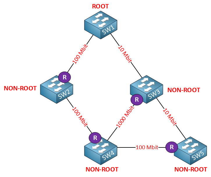
Here’s the topology I will use to explain the spanning-tree cost calculation:
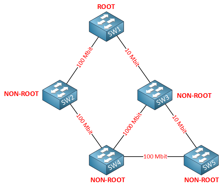
In the picture above, we have a larger network with multiple switches. You can also see that there are different interface types. We have Ethernet (10 Mbit), FastEthernet (100Mbit), and Gigabit (1000Mbit). SW1 on top is the root bridge so all other switches are non-root and need to find the shortest path to the root bridge.
| Bandwidth | Cost |
| 10 Mbit | 100 |
| 100 Mbit | 19 |
| 1000 Mbit | 4 |
Spanning tree uses cost to determine the shortest path to the root bridge. The slower the interface, the higher the cost is. The path with the lowest cost will be used to reach the root bridge.
Here’s where you can find the cost value:
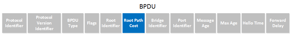
In the BPDU, you can see a field called root path cost. This is where each switch will insert the cost of its shortest path to the root bridge. Once the switches find out which switch is declared as root bridge, they will look for the shortest path to get there. BPDUs will flow from the root bridge downwards to all switches.
Here’s an example of the different spanning tree costs for our topology:
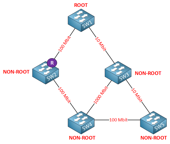
SW2 will use the direct link to SW1 as its root port since this is a 100 Mbit interface and has a cost of 19. It will forward BPDUs towards SW4; in the root path cost field of the BPDU, you will find a cost of 19. SW3 is also receiving BPDUs from SW1, so it’s possible that, at this moment, it selects its 10 Mbit interface as the root port. Let’s continue…
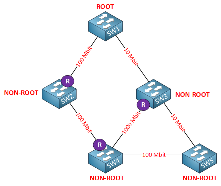
This picture needs some more explanation, so let me break it down:
- SW3 receives BPDUs on its 10 Mbit interface (cost 100) and on its 1000 Mbit interface (cost 4). It will use its 1000 Mbit interface as its root port (the shortest path to the root bridge is 19+19+4=42).
- SW3 will forward BPDUs to SW4. The root path cost field will be 100.
- SW4 receives a BPDU from SW2 with a root path cost of 19.
- SW4 receives a BPDU from SW3 with a root path cost of 100.
- The path through SW2 is shorter, so this will become the root port for SW4.
- SW4 will forward BPDUs towards SW3 and SW5. In the root path cost field of the BPDU, we will find a cost of 38 (its root path cost of 19 + its own interface cost of 19).
- SW3 will forward BPDUs towards SW5 and insert a cost of 42 in the root path cost field (19 + 19 + 4).
The complete picture will look like this:
SW5 receives BPDUs from SW3 and SW4. In the BPDU, we will look at the root path cost field, and we’ll see the following information:
- BPDU from SW3: cost 42
- BPDU from SW4: cost 38
SW5 will add the cost of its interface towards SW4, so the total cost to reach the root bridge through SW4 is 38 + 19 (cost of 100 Mbit interface) = 57. The total cost to reach the root bridge through SW3 is 42 + 100 (10 Mbit interface) = 142. As a result, it will select the interface towards SW4 as its root port.
Are you following me so far? Keep in mind that switches only make decisions on the BPDUs that they receive! They have no idea what the topology looks like. The only thing they do know is on which interface they received the best BPDU. The best BPDU is the one with the shortest path to the root bridge!
What if the cost is equal?
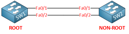
Take a look at the picture above. SW1 is the root bridge, and SW2 is non-root. We have two links between these switches so that we have redundancy. Redundancy means loops so spanning tree is going to block one the interfaces on SW2.
SW2 will receive BPDUs on both interfaces, but the root path cost field will be the same! Which one are we going to block? Fa0/1 or fa0/2? When the cost is equal spanning tree will look at the port priority. By default, the port priority is the same for all interfaces, which means that the interface number will be the tie-breaker.
Andy if I understand your question correctly then I think no. The lowest switch port number is a local decision therefore it is not considering the port numbers of the upstream switch. Maybe someone will correct me.
I also can be wrong…
Marek
In the calculation , the switch , receive a bdpu with root path cost value ( the link cost is given by costs Of the 2 port ,upstream and downstream)
The switch add at this path cost value , cost Of the port whrere receive the bpdu… When sendig this bpdu out another port, the switch shoulds also add the cost Of the port which use to forward??
Hi Francesco,
The switch will add the cost of its root port when it forwards the BPDU. It never adds the cost of the interface that is used to send the BPDU.
The total cost to get to the root will be the sum of all root ports.
Rene
thanks so much—