If you are familiar with switches and VLANs you might know that you require a router if you want to communicate between VLANs. In this lesson, I’ll show you how you can use a router connected to a single switch as a “router on a stick”.
This is the topology we’ll use:
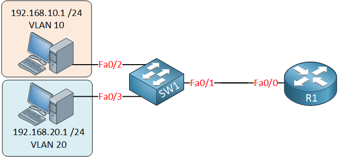
On the switch, we have VLAN 10 and VLAN 20, and there’s only a single cable between the router and the switch. The router needs access to both VLANs, so the link between the router and switch will be a trunk!
It’s possible to create sub-interfaces on a router. These are virtual interfaces, and on each sub-interface, we can configure an IP address, basically, it looks like this:
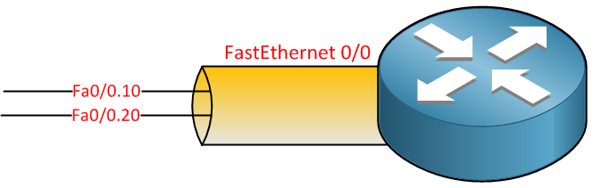
You can pick any number that you like, but I decided to use the VLAN numbers, one sub-interface for VLAN 10 and another for VLAN 20.
Here’s what the configuration looks like on the router:
R1(config)#interface fastEthernet 0/0
R1(config-if)#no shutdown
R1(config-if)#exit

R1(config)#interface fastEthernet 0/0.10
R1(config-subif)#encapsulation dot1Q 10
R1(config-subif)#ip address 192.168.10.254 255.255.255.0
R1(config-subif)#exit

R1(config)#interface fastEthernet 0/0.20
R1(config-subif)#encapsulation dot1Q 20
R1(config-subif)#ip address 192.168.20.254 255.255.255.0
Above, you can see my two sub-interfaces and the IP addresses I assigned. IP address 192.168.10.254 will be the default gateway for computers in VLAN 10 and 192.168.20.254 for computers in VLAN 20.
One important command isencapsulation dot1Q. There is no way for our router to know which VLAN belongs to which sub-interface, so we have to use this command. Fa0/0.10 will belong to VLAN 10 and Fa0/0.20 to VLAN 20. Let’s check the routing table:
R1#show ip route
Codes: C - connected, S - static, R - RIP, M - mobile, B - BGP
       D - EIGRP, EX - EIGRP external, O - OSPF, IA - OSPF inter area
       N1 - OSPF NSSA external type 1, N2 - OSPF NSSA external type 2
       E1 - OSPF external type 1, E2 - OSPF external type 2
       i - IS-IS, su - IS-IS summary, L1 - IS-IS level-1, L2 - IS-IS level
       ia - IS-IS inter area, * - candidate default, U - per-user static
       o - ODR, P - periodic downloaded static route

Gateway of last resort is not set

C    192.168.10.0/24 is directly connected, FastEthernet0/0.10
C    192.168.20.0/24 is directly connected, FastEthernet0/0.20
You can see both sub-interfaces in the routing table. This allows the router to route between the two VLANs. That’s all there is to it! Configure your computers so that the router’s IP address for the corresponding VLAN is their default gateway, and you are ready to go.
How does the configuration on the switch look like? If the switch is just a simple Cisco Layer 2 switch, do we need to create the VLAN SVIs?
i had that done on the router,
What else has to be done on the switch?
thanks
First, thank you for your helpful lesson. I have a question about vlan and this lesson. One reason for making vlan is security. If we do this (Router on a Stick) don’t you think we eliminate this security? Afterward every vlan can get to other vlan?
Thanks in Advance
Hi Reza,
Good question and there’s a good answer to it. Each VLAN uses a different subnet and if you want communication between VLANs it has to be routed. On the router we can use access-lists to filter on layer 3 (IP addresses / subnets) and also on layer 4 (protocol and port numbers). This allows you to block certain traffic between VLAN.
Best Regards,
Rene
Hi Regina,
The configuration on the Cisco switch is pretty straightforward. The interface connected to the router has to be a trunk:
And the interfaces that connect to the host are regular access ports:
interface fa0/1
You don’t need to use VLAN SVIs…a layer 2 switch uses the SVI only for management purposes. A layer 3 switch uses a SVI per VLAN which hosts can use as default gateway (in that case you don’t need a
... Continue reading in our forum