Frame-relay is one of the WAN protocols you need to understand if you plan to become CCNA certified. It’s also one of the most difficult protocols to understand for most CCNA students. In this lesson I’ll explain to you why we use(d) frame-relay and how it works.
Before we start looking at frame relay let me tell you a little story. We have a network with four sites:
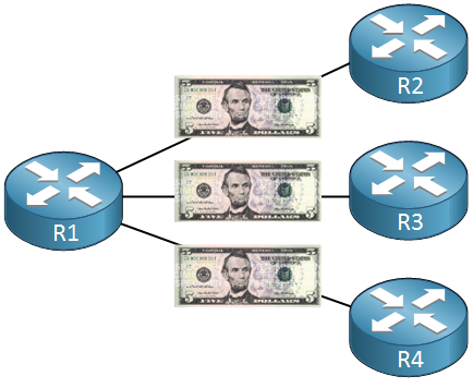
There’s R1, R2, R3 and R4. Since we want connectivity between the sites we have an ISP who sold us three leased lines:
- Between R1 and R2.
- Between R1 and R3.
- Between R1 and R4.
Using leased lines is awesome! You are the only person using these lines since you are paying for them. This means high quality and probably a low chance of congestion (if you have fast links). It’s also pretty secure since it’s only your traffic that’s flowing through these lines.
There are also a few downsides to using leased lines however:
- You are the only one using these lines so you gotta pay for them, being exclusive is fun but expensive.
- On R1 you’ll need three interfaces for each leased line, more interfaces means more money.
- What happens if you are going to move the site R1? It’s not always possible to move the leased lines with you.
- What if the R1 crashes? R2, R3 and R4 will be isolated as well.
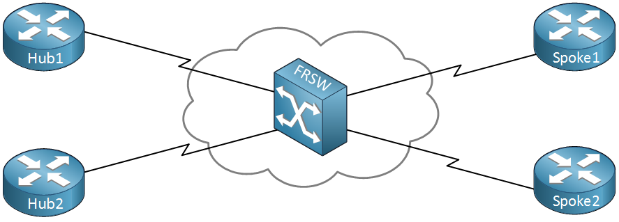
This is a picture of frame relay and it works a bit different. The idea behind frame relay is that you have a single infrastructure from the service provider and multiple customers are connected to it, effectively sharing everything.
In the middle you see a cloud with an icon you probably haven’t seen before. This icon is the frame relay switch. The cloud is called the frame relay cloud and the reason it has this name is because for us as customer it’s unknown what happens in the frame relay cloud. This is the service provider’s infrastructure and we really don’t care what happens there…we are the customer and all we want is connectivity!
What else do you see? There are two customers (1 and 2) and each of them has a Headquarters (Hub) and a branch office (Spoke).
One more picture, here’s a frame relay network with three routers from one company:
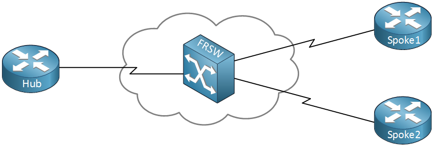
There’s a router at the headquarters (Hub) and we have two branch offices (Spoke1 and Spoke2). All of them are connected to the frame relay cloud.
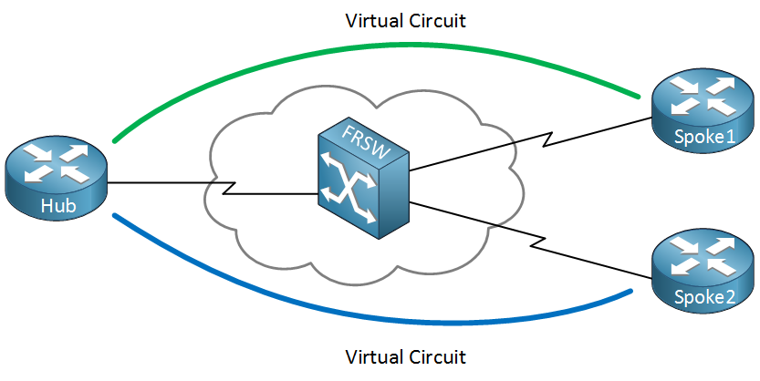
We call our service provider since we want connectivity and the first question they’ll ask us is which sites should be connected?. In the example above you can see two virtual circuits, the green and blue one. With frame relay there’s a difference between the physical and logical connections. The physical connection is just the serial cable which is connected to the provider. Our logical links are virtual circuits. As you can see there is a virtual circuit from Spoke1 to the Hub and another one from Spoke2 to the Hub.
This means that we can send traffic through our virtual circuits between:
- Spoke1 and Hub.
- Spoke2 and Hub.
There is no virtual circuit between Spoke1 and Spoke2. Does this mean there is no connectivity between them? No you can still have connectivity between them by sending data to the Hub! Of course you can get another virtual circuit between Spoke1 and Spoke2 but you’ll have to pay for it. Virtual circuits are also called PVC (Permanent Virtual Circuit).
You also pay for a certain speed called the CIR (Committed Information Rate). The cool thing about frame relay is that when no other customers are using the frame relay network it’s possible you get a higher speed than what you paid for…the CIR however is a speed that is guaranteed.
How do we know if a PVC is working or not?
Frame-relay uses something called LMI which stands for Local Management Interface. LMI has two functions:
- It’s a keepalive mechanism.
- It tells us if the PVC is active or inactive.
- It also gives us a DLCI (Data Link Connection Identifier). I’ll get back to this in a bit
There are 3 types of LMI. They all do the same thing but there are three standards which are not compatible with each other. Whatever you choose make sure it’s the same between two devices:
- Cisco
- ANSI T1.617 Annex D
- ITU-T Q.933 Annex A
So if you pick Cisco on one side, use Cisco on the other side as well.
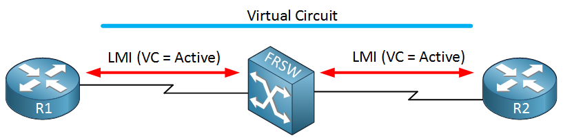
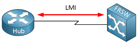
Here’s an example of LMI in action. In the middle we have the frame relay switch. LMI packets are sent between R1 and the frame relay switch and R2 and the frame relay switch. The frame relay switch tells our routers that the PVC is active.
What else do you need to know about frame relay? Let me show you the OSI model:
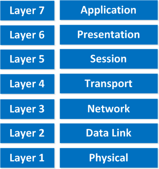
WAN protocols describe the physical (layer 1) and data link (layer 2). What does frame relay use on the data link layer? We don’t use MAC addresses since that’s Ethernet but we do have something else called a DLCI (Data Link Connection Identifier).
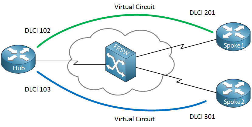
For each PVC you will get a DLCI per router. In our example above you can see that for the PVC between the Hub and Spoke1, we have DLCI 102 on the Hub and DLCI 201 on Spoke1.
Between the Hub and Spoke2, we have DLCI 103 on the Hub and DLCI 301 on Spoke2. Our DLCI is nothing more but a unique identifier for the data link layer per PVC.
Now there is an important concept to grasp and remember about DLCI. DLCI’s are only locally known to the router! Your router does not know the DLCI of the router on the other side. This is different if you compare it to Ethernet. In our Ethernet world you need to know the MAC address of the computer on the other side in order to send something to it.
This is just like taking a train. If you are at the train station you walk to the correct train platform and take the train. You have no idea on which train platform you will arrive and you don’t care.
Frame-relay supports multiple topologies:
- Full-mesh
- Partial-mesh
- Hub and Spoke
Let me show you an example of each topology type:
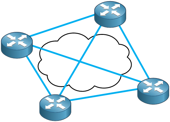
This is our full-mesh topology. As you can see there is a PVC between every router.
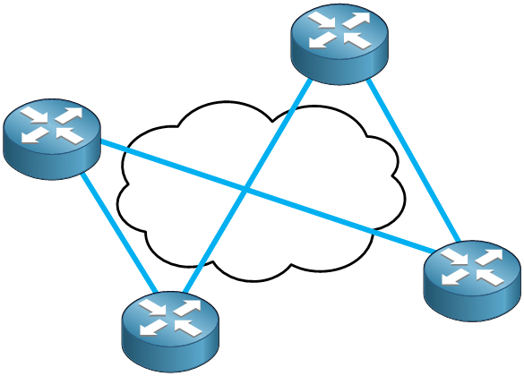
This is partial-mesh. The more important routers will have multiple connections to others.
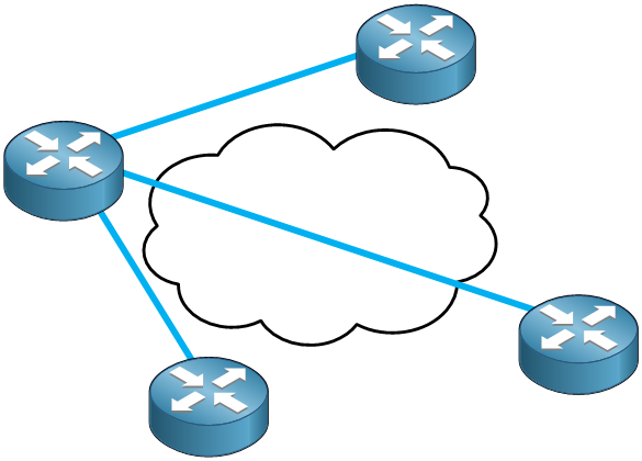
This is the hub and spoke model. The router on the left is our hub and the other routers are spokes. If the spokes want to communicate with each other they’ll have to send traffic towards the hub router.
Keep this in mind.
What it means is that frame relay is multi-access since all routers can access the network but you are unable to send broadcasts over the frame relay network. No broadcast also means you are unable to send multicast traffic. No multicast means you’ll be in trouble with routing protocols. Rip version 2, OSPF and EIGRP all use multicast. Does this mean you can’t use routing protocols with frame relay? Well no but it’s a bit tricky:
- RIP, OSPF and EIGRP can also use unicast instead of multicast.
- There is a method to “emulate” broadcasts over your frame relay network.
What other problems might we encounter with frame relay and routing? Do you remember the characteristics of distance vector routing protocols (RIP and EIGRP)?
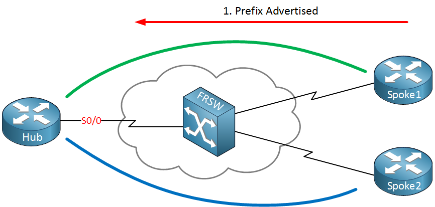
In the picture above I have configured RIP on all the routers. Spoke1 is sending routing information towards the Hub. If we look at the routing table we see this routing information on the Hub.
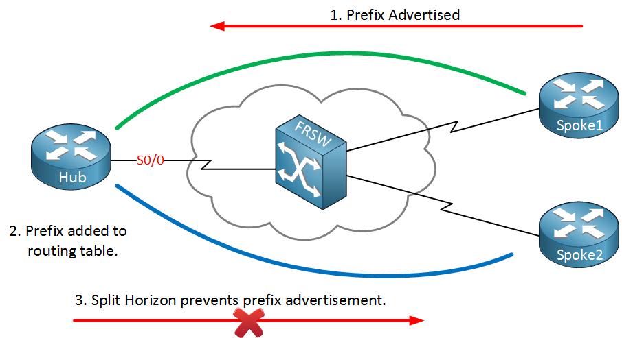
Do you remember the split-horizon rule? Whatever you learn from your neighbor you don’t advertise back to them. To be more specific: whatever you learn on an interface you don’t advertise it back out on the same interface.
We are using two PVC’s but on the Hub there is still only one physical interface. Split-horizon will prevent the advertisement of routing information towards Spoke2.
How can we solve this problem?
- You can disable split horizon (the default on physical interfaces).
- You can use sub-interfaces.
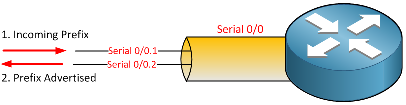
If you use a sub-interface you don’t have the split-horizon problem since you are learning routing information on serial0/0.1 and advertising it out of serial0/0.2
Frame-relay can use point-to-point sub-interfaces or point-to-multipoint sub-interfaces. If you use point-to-point it will solve your split-horizon problem but you’ll need to use a different IP subnet per PVC. Point-to-multipoint means you have the split-horizon problem but you can use a single IP subnet for all PVCs.
Remember ARP (address resolution protocol)? When we use ARP for Ethernet we need to learn the MAC address of the computer we want to send something to. ARP effectively maps the destination IP address to the destination MAC address.
Frame-relay uses inverse ARP and is a bit different. Remember my story about the train platform and how your router only knows it’s local DLCI? You don’t know the DLCI of the other side. Inverse ARP is going to map your local DLCI to the IP address of the other side:
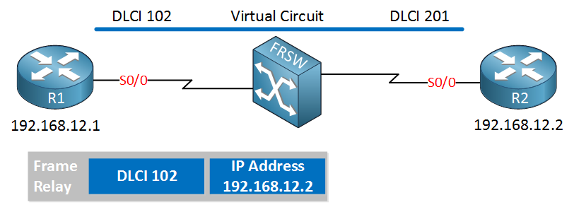
R1 in my example above has mapped the IP address of R2 (192.16.12.2) to its local DLCI 102. That’s inverse ARP.
Hi Rene,
This is very good explanation about frame realy to understand frame-realy technology.
Thanks so much for giving this information to all Networking negineers.
I am doing CCIE Security please help me how to do the study for CCIE security because I am doing job as well in IT MNC company.
Khandesha Kothale
Router Frodo will now know it can reach IP address 192.168.12.1 by sending traffic through the PVC with DLCI 102. Router Gandalf will know that it can reach IP address 192.168.12.1 through the PVC with DLCI 201.
its should be 192.168.12.2 if i am ri8 by sending traffic through dlci 102
Hi Anirban,
You are right, just fixed this error.
Rene
Nice explanation Rene…keep up the good work…
simply put and understandable, though i have a small doubt.
The commands:
Do these two commands mean the same thing? i have tried using either one of them and frame-relay just works fine.. its created this confusion , whether one of the commands might have a different purpose. e.g . like on a frame-relay switch or something???