Lesson Contents
Congratulations! You’ve been selected as the chief network engineer for NovaTech Pioneers, an emerging leader in the realm of digital innovation. With the company poised for unprecedented growth, a brand-new campus is on the horizon to house its expanding operations and ambitious projects.
Your pivotal role involves constructing a sophisticated campus network from the ground up. This network is the heartbeat of NovaTech Pioneers, designed to underpin a wide array of activities, from cutting-edge research to global collaboration.
As you embark on this comprehensive journey, here’s what you can expect to engage with in bringing the NovaTech Pioneers campus network to life:
- LAN Switching Technologies: Your first steps involve VLAN setup for network segmentation and security, trunking to facilitate efficient switch connections, and implementing Spanning Tree Protocol (STP) for network resilience and loop prevention.
- Layer 3 Implementations: Advance to configuring IP addresses for device communication and routing, ensuring packets navigate the network efficiently. You’ll work with both static routes and dynamic routing protocols.
- IP Services: Set up Dynamic Host Configuration Protocol (DHCP) for dynamic IP address assignment, Network Address Translation (NAT) for secure internet access, and Virtual Router Redundancy Protocol (VRRP) for router failover and high availability.
- Network Management: Implement Network Time Protocol (NTP) to synchronize network devices, essential for accurate logging and event management. Syslog for reliable logging. Security will be a continuous focus, safeguarding every network layer.
- Security: Improve the network’s security such as using access-lists to restrict traffic, configure SSH for secure remote login, and more.
This lab is a proving ground where theory meets practice, designed to challenge you and foster a deep understanding of network component interactions. You’ll develop a robust set of skills and best practices vital for a network engineer.
Your expertise will drive NovaTech Pioneers into a new era. It’s time to unleash your potential and create a network that is not only scalable and reliable but also a foundation for the company’s visionary goals. Welcome to NovaTech Pioneers, where your journey in shaping the future of networking begins.
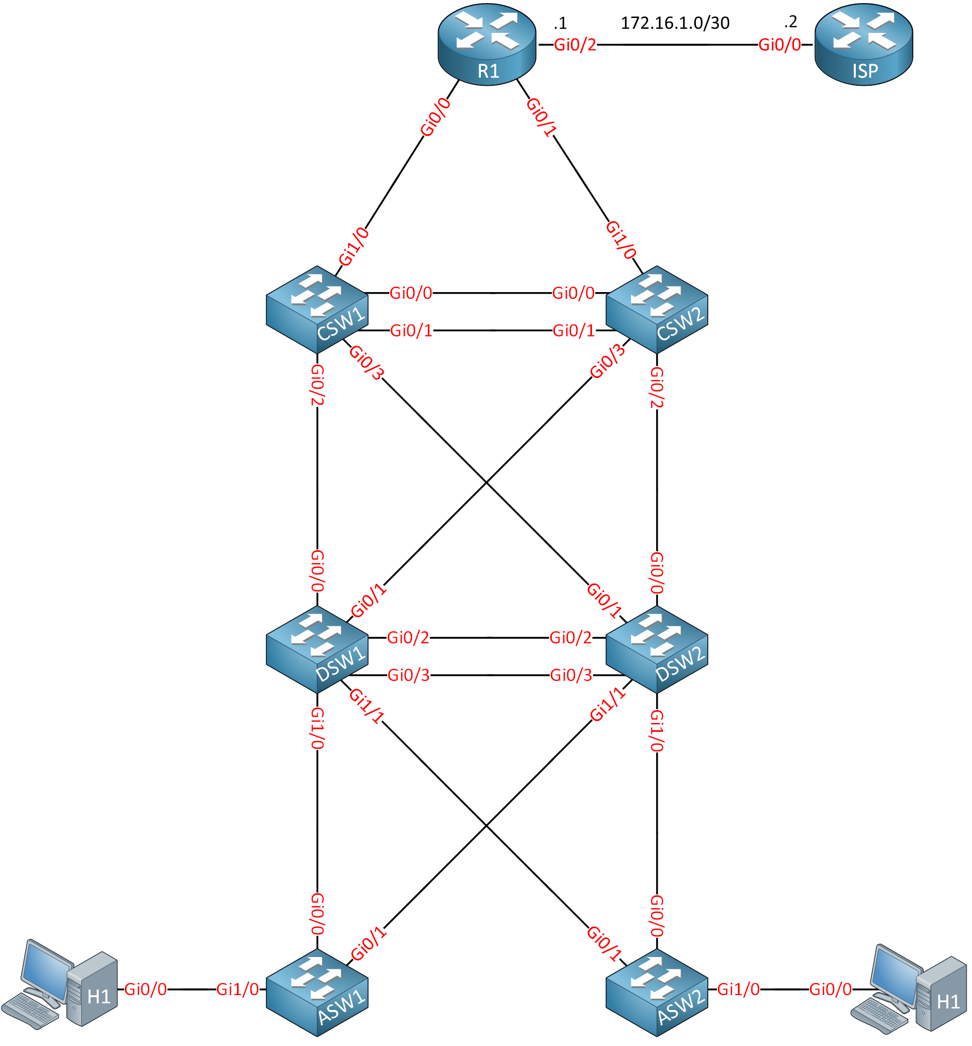
Topology
Here is the topology for this lab:
Startup Configs
Configurations
Want to take a look for yourself? Here you will find the startup configuration of the ISP router.
ISP
hostname ISP
!
ip cef
ipv6 unicast-routing
ipv6 cef
!
interface Loopback0
 ip address 1.1.1.1 255.255.255.255
 ipv6 address 2001:DB8::1:1:1:1/128
!
interface GigabitEthernet0/0
 ip address 172.16.1.2 255.255.255.252
 duplex auto
 speed auto
 media-type rj45
 ipv6 address 2001:DB8:0:131::1F/127
 ipv6 enable
!
ip http server
!
ipv6 route ::/0 2001:DB8:0:131::1E
!
end
Tasks
The tasks are described as if you are on the job, and someone asks you to configure this network. It’s not a cookbook where we tell exactly what to do and in what order. This helps you think through what is really needed instead of just typing in commands.
Basics
- Each device should have a configured hostname.
- Logging messages on R1 should never interrupt what you are typing on the CLI.
- The console log on R1 should never timeout if you are idle.
- The interfaces on the core switches that connect to R1 require a description so you know what the interfaces are for.
- When you mistype a command on R1, it shouldn’t attempt to connect to a hostname.
LAN Switching Technologies
- The campus network requires the following VLANs:
- VLAN 10: CLIENTS
- VLAN 20: VOICE
- VLAN 30: PRINTERS
- VLAN 40: MANAGEMENT
- H1 and H2 should be assigned to VLAN 10.
- Prepare interface GigabitEthernet 0/2 on ASW1 so that the interface can connect to a computer in VLAN 10 and a phone in VLAN 20.
- Configure required trunks between the access and distribution layer switches:
- The access layer switches should use a dynamic method to negotiate the trunk link.
- The distribution layer switches should use a static method to create a trunk.
- The links between the distribution layer switches have to be bundled:
- You need to use a negotiation, but due to company policy, you are not allowed to use a proprietary protocol.
- DSW1 should actively negotiate, while DSW2 should only respond to requests.
- The links between the core layer switches have to be bundled:
- You are not allowed to use any protocols to establish this link.
- Configure the network so that we use the fastest spanning tree protocol option. A spanning tree should be calculated for every VLAN.
- The DSW1 switch has to be the root bridge for all VLANs. When this switch fails, SW2 should take over.
- The hosts are modern computers that boot up in a couple of seconds. Make sure that when they are connected, they can send traffic immediately, and they don’t have to wait for the network to converge.
- The security officer fears malicious hosts might attempt to influence the spanning tree protocol. Here are your requirements to deal with this:
- When a host sends a BPDU, the interface should go down immediately.
- The interface should recover automatically after 10 minutes.
- Company policy dictates that you should use different timers for spanning tree:
- Spanning tree BPDUs should be sent every three seconds.
- The port state should transition after ten seconds when a new configuration BPDU propagates throughout the network.
- A configuration BPDU should expire after 20 seconds.
- Make sure these timers are always used, even when another switch becomes the root bridge.
IP Addressing
The campus network requires IPv4 and IPv6 addressing.
IPv4
Here are the requirements for IPv4:
- The campus network has to use the 10.0.0.0/8 prefix.
- The VLANs have the following requirements:
- VLAN 10: contains a maximum of 100 devices.
- VLAN 20: contains a maximum of 40 devices.
- VLAN 30: contains a maximum of 12 devices.
- VLAN 40: contains a maximum of 6 devices.
- Each device requires a loopback interface with a /32 IP address.
- Point-to-point links require IP addresses (when needed)
- The link between R1 and ISP uses the 172.16.1.0/30 subnet:
- R1: 172.16.1.1
- ISP: 172.16.1.2
You must be as efficient as possible with IP address space while considering future growth for new network devices and VLANs. The number of devices per VLAN will not change in the future. Configure all IPv4 addresses.
IPv6
Here are the requirements for IPv6:
- You must use the 2001:db8::/32 prefix.
- Create an addressing scheme and take this into account:
- VLANs: use a /64 prefix.
- Loopback interfaces: Use a /128 prefix.
- Point-to-point links: Use a /127 prefix.
Configure all IPv6 addresses.
Routing Technologies
The campus network requires IPv4 and IPv6 routing.
IPv4
Here are the IPv4 requirements:
- Configure R1 so that you can reach 1.1.1.1 or any other network behind the ISP router. You are not allowed to make any changes to the ISP router.
- Configure the campus network so all VLANs, point-to-point links, and loopback interfaces are reachable:
- You must use a non-proprietary link-state routing protocol that converges quickly.
- All devices should be in a single area.
- Distribution layer switches shouldn’t have any unnecessary neighbor adjacencies.
- The core layer switches should not have a DR/BDR election on their bundled interface.
- The core layer switches neighbor adjacency requires fast convergence:
- A hello packet should be sent every 5 seconds.
- The neighbor adjacency should be declared down after not receiving hello packets for 15 seconds.
- All loopback and VLAN interfaces should be reachable.
IPv6
Here are the IPv6 requirements:
- Configure R1 so that you can reach 2001:DB8::1:1:1:1 or any other network behind the ISP router. You are not allowed to make any changes to the ISP router.
- Configure internal routing on all campus network devices:
- Use the IPv4 address on the loopback interfaces as the router ID.
- Use a single area.
- Ensure there are no unneeded neighbor adjacencies between the distribution layer switches.
- Advertise a default route on R1 in the routing protocol.
- All loopback and VLAN interfaces should be reachable.
Network Services
Users in VLAN 10 have been complaining that their default gateway sometimes becomes unreachable. This happens because of stability issues on DSW1 and DSW2.
- Configure a virtual default gateway address for VLAN 10 so that this won’t cause any more issues.
Hosts should be able to receive IP addresses automatically:
- Configure a pool on R1 for VLAN 10 with these requirements:
- Use the virtual gateway address as the default gateway.
- Use DNS server 1.1.1.1.
- Use domain name MYDOMAIN.LOCAL
- Lease time 48 hours.
- Configure a pool on R1 for VLAN 20 and include the IP address of TFTP server 10.0.0.135.
- Test the IP address assignment by disabling routing on H1 and H2 and enable the DHCP client.
Users request access to the server on 1.1.1.1:
- Configure R1 so that all campus switches and hosts can reach 1.1.1.1.
- You are not allowed to make any changes to the ISP router.
The security officer noticed that the logging information was inconsistent. To solve this, all clocks on the switches have to be synchronized:
- R1 should use 1.1.1.1 as the time source.
- Core layer switches should use R1 as the time source.
- Distribution layer switches should use the core switches as a time source.
- Access layer switches should use the distribution layer switches as a time source.
Security
The company policy requires some security measures:
- When someone logs into R1, it should show an “authorized users only” message.
- CSW1 should show a MOTD message “This is CSW1”.
- Interface GigabitEthernet1/0 on ASW1 which connects to H1 should be protected:
- Only a single MAC address is allowed.
- The first learned MAC address should be stored.
- When there is a violation, the interface should be shut.
- Hosts in VLAN 10 are not allowed to reach the HTTP server on 1.1.1.1. All other traffic is permitted.
Network Management
- DSW1 requires an external syslog server located at 10.0.0.240.
- Configure the Cisco proprietary discovery protocol so that switches and R1 can learn about each other:
- Messages should be sent every five seconds.
- When a device doesn’t receive any messages, information should be discarded after 60 seconds.
- Messages should not be sent to hosts or the ISP.
- Configure a non-proprietary discovery protocol on the access layer switches:
- Don’t send or receive messages on the interfaces that connect to the distribution layer switches.
- Don’t send any messages to hosts but you should receive them.
- CSW1 should be configured so that you can connect to it remotely in a secure way:
- Use username “cisco” with password “cisco”.
- The password should not be stored in clear text.
- Telnet traffic should not be permitted.
Solution
This lab was configured using these images:
- Switches: Cisco IOS Software, vios_l2 Software (vios_l2-ADVENTERPRISEK9-M), Experimental Version 15.2(20200924:215240) [sweickge-sep24-2020-l2iol-release 135]
- Routers: Cisco IOS Software, IOSv Software (VIOS-ADVENTERPRISEK9-M), Version 15.9(3)M6, RELEASE SOFTWARE (fc1)
Basics
We’ll start with the basics. Use enable and configure terminal to start the configuration. If you are unsure about how the Cisco CLI works, take a look at our Introduction to Cisco IOS CLI lesson.
Hostname
We’ll start with the hostname on all devices:
inserthostname-here(config)#hostname R1inserthostname-here(config)#hostname ASW1inserthostname-here(config)#hostname DSW1inserthostname-here(config)#hostname DSW2inserthostname-here(config)#hostname CSW1inserthostname-here(config)#hostname CSW2inserthostname-here(config)#hostname H1inserthostname-here(config)#hostname H2After changing the hostname, it shows up right away on the CLI:
R1(config)#The hostname also shows up in the running configuration:
R1#show running-config | include hostname
hostname R1
Logging Synchronous
Logging synchronous appends commands to a new line. This can be useful if you don’t want to interrupt what you are typing on the CLI:
R1(config)#line console 0
R1(config-line)#logging synchronous
Exec Timeout
If you don’t want the console line to log out because it’s idle, you can use the exec timeout command. Here is the default setting:
R1#show line console 0
   Tty Typ     Tx/Rx    A Modem  Roty AccO AccI   Uses   Noise  Overruns   Int
*     0 CTY              -    -      -    -    -      0       0     0/0       -

Line 0, Location: "", Type: ""
Length: 24 lines, Width: 80 columns
Status: PSI Enabled, Ready, Active, Automore On
Capabilities: none
Modem state: Ready
Group codes:    0
Modem hardware state: CTS* noDSR  DTR RTS
Special Chars: Escape  Hold  Stop  Start  Disconnect  Activation
                ^^x    none   -     -       none
Timeouts:      Idle EXEC    Idle Session   Modem Answer  Session   Dispatch
                00:10:00       never                        none     not set
                            Idle Session Disconnect Warning
                              never
                            Login-sequence User Response
                             00:00:30
                            Autoselect Initial Wait
                              not set
Modem type is unknown.
Session limit is not set.
Time since activation: 00:12:09
Editing is enabled.
History is enabled, history size is 20.
DNS resolution in show commands is enabled
Full user help is disabled
Allowed input transports are none.
Allowed output transports are lat pad telnet rlogin lapb-ta mop v120 ssh.
Preferred transport is lat.
Shell: disabled
Shell trace: off
No output characters are padded
No special data dispatching characters
The default idle timeout is 10 minutes. We’ll set it to 0 which disables it:
R1(config)#line console 0
R1(config-line)#exec-timeout 0 0
Now it shows up as “never”:
R1#show line console 0
   Tty Typ     Tx/Rx    A Modem  Roty AccO AccI   Uses   Noise  Overruns   Int
*     0 CTY              -    -      -    -    -      0       0     0/0       -

Line 0, Location: "", Type: ""
Length: 24 lines, Width: 80 columns
Status: PSI Enabled, Ready, Active, Automore On
Capabilities: none
Modem state: Ready
Group codes:    0
Modem hardware state: CTS* noDSR  DTR RTS
Special Chars: Escape  Hold  Stop  Start  Disconnect  Activation
                ^^x    none   -     -       none
Timeouts:      Idle EXEC    Idle Session   Modem Answer  Session   Dispatch
                never         never                        none     not set
                            Idle Session Disconnect Warning
                              never
                            Login-sequence User Response
                             00:00:30
                            Autoselect Initial Wait
                              not set
Modem type is unknown.
Session limit is not set.
Time since activation: 00:12:09
Editing is enabled.
History is enabled, history size is 20.
DNS resolution in show commands is enabled
Full user help is disabled
Allowed input transports are none.
Allowed output transports are lat pad telnet rlogin lapb-ta mop v120 ssh.
Preferred transport is lat.
Shell: disabled
Shell trace: off
No output characters are padded
No special data dispatching characters
Interface Description
Interface descriptions can be useful to quickly see what the interface is used for. This is how to configure one:
CSW1(config)#interface GigabitEthernet 1/0
CSW1(config-if)#description LINK-TO-R1CSW2(config)#interface GigabitEthernet 1/0
CSW2(config-if)#description LINK-TO-R1You can see the description here:
CSW1#show interfaces GigabitEthernet 1/0 | include Description
  Description: LINK-TO-R1
DNS Lookups
When you mistype a command, Cisco IOS thinks you want to connect to a hostname. For example:
R1#hello
Translating "hello"...domain server (255.255.255.255)
 (255.255.255.255)
Translating "hello"...domain server (255.255.255.255)

% Bad IP address or host name
% Unknown command or computer name, or unable to find computer address
This can be annoying when you don’t have a DNS server configured because it takes time. You can disable it like this:
R1(config)#no ip domain-lookupOnce configured, Cisco IOS won’t attempt to do a DNS lookup anymore:
R1#hello
Translating "hello"

Translating "hello"

% Bad IP address or host name
% Unknown command or computer name, or unable to find computer address
LAN Switching Technologies
This is where we configure all L2 technologies.
VLANs
We need to configure VLANs.
Basic VLAN
We’ll manually create all VLANs on the required switches:
ASW1, ASW2, DSW1, DSW2
(config)#vlan 10
(config-vlan)#name CLIENTS

(config)#vlan 20
(config-vlan)#name VOICE

(config)#vlan 30
(config-vlan)#name PRINTERS

(config)#vlan 40
(config-vlan)#name MANAGEMENT
We only use VLANs on the access and distribution layer switches.
This is how you can check the VLANs you create:
ASW1#show vlan

VLAN Name                             Status    Ports
---- -------------------------------- --------- -------------------------------
1    default                          active    Gi0/0, Gi0/1, Gi0/2, Gi0/3
                                                Gi1/0
10   CLIENTS                          active
20   VOICE                            active
30   PRINTERS                         active
1002 fddi-default                     act/unsup
1003 token-ring-default               act/unsup
1004 fddinet-default                  act/unsup
1005 trnet-default                    act/unsup

VLAN Type  SAID       MTU   Parent RingNo BridgeNo Stp  BrdgMode Trans1 Trans2
---- ----- ---------- ----- ------ ------ -------- ---- -------- ------ ------
1    enet  100001     1500  -      -      -        -    -        0      0
10   enet  100010     1500  -      -      -        -    -        0      0
20   enet  100020     1500  -      -      -        -    -        0      0
30   enet  100030     1500  -      -      -        -    -        0      0
1002 fddi  101002     1500  -      -      -        -    -        0      0
1003 tr    101003     1500  -      -      -        -    -        0      0
1004 fdnet 101004     1500  -      -      -        ieee -        0      0
1005 trnet 101005     1500  -      -      -        ibm  -        0      0

Remote SPAN VLANs
------------------------------------------------------------------------------

Primary Secondary Type              Ports
------- --------- ----------------- ------------------------------------------
The VLANs with their names are created.
Switchport VLAN Assignment
The interfaces that connect to H1 and H2 need to be in VLAN 10:
ASW1 & ASW2
(config)#interface GigabitEthernet 1/0
(config-if)#switchport mode access
(config-if)#switchport access vlan 10
Because these are interfaces that connect to hosts, it’s best to change the switchport mode to access. If you leave them at the default, a host could try to create a trunk to your switch.
You can see the assigned interfaces to each VLAN in this overview:
ASW1#show vlan

VLAN Name                             Status    Ports
---- -------------------------------- --------- -------------------------------
1    default                          active    Gi0/0, Gi0/1, Gi0/2, Gi0/3
10   CLIENTS                          active    Gi1/0
20   VOICE                            active
[output omitted]
Or you can look at the switchport settings per interface:
ASW1#show interfaces GigabitEthernet 1/0 switchport
Name: Gi1/0
Switchport: Enabled
Administrative Mode: static access
Operational Mode: static access
Administrative Trunking Encapsulation: negotiate
Operational Trunking Encapsulation: native
Negotiation of Trunking: Off
Access Mode VLAN: 10 (CLIENTS)
Voice VLAN
You can assign a Voice VLAN to an interface using the switchport voice command. Here is how to do this:
ASW1(config)#interface GigabitEthernet 0/2
ASW1(config-if)#switchport mode access
ASW1(config-if)#switchport access vlan 10
ASW1(config-if)#switchport voice vlan 20
We can verify the voice VLAN per interface like this:
ASW1#show interfaces GigabitEthernet 0/2 switchport
Name: Gi0/2
Switchport: Enabled
Administrative Mode: static access
Operational Mode: static access
Administrative Trunking Encapsulation: negotiate
Operational Trunking Encapsulation: native
Negotiation of Trunking: Off
Access Mode VLAN: 10 (CLIENTS)
Trunking Native Mode VLAN: 1 (default)
Administrative Native VLAN tagging: enabled
Voice VLAN: 20 (VOICE)
Trunks
We need trunks between the access layer and distribution layer switches. The default switchport state looks like this:
ASW1#show interfaces GigabitEthernet 0/0 switchport | include Mode
Administrative Mode: dynamic auto
Operational Mode: static access
Access Mode VLAN: 1 (default)
Trunking Native Mode VLAN: 1 (default)
Capture Mode Disabled
It is dynamic auto, and the operational mode becomes access. We’ll change the interfaces to dynamic desirable:
ASW1 & ASW2
(config)#interface range GigabitEthernet 0/0 - 1
(config-if-range)#switchport mode dynamic desirable
The end result will be a trunk port:
ASW1#show interfaces GigabitEthernet 0/0 switchport | include Mode
Administrative Mode: dynamic desirable
Operational Mode: trunk
Access Mode VLAN: 1 (default)
Trunking Native Mode VLAN: 1 (default)
Capture Mode Disabled
The interfaces on the distribution layer switches that connect to the access layer switches have to be configured in static trunk mode:
DSW1 & DSW2
(config)#interface range GigabitEthernet 1/0 - 1
(config-if-range)#switchport trunk encapsulation dot1q
(config-if-range)#switchport mode trunk
This won’t change the end result because the interfaces are already in trunk mode, but it was a requirement.
Let’s verify our work:
DSW1#show interfaces GigabitEthernet 1/0 switchport
Name: Gi1/0
Switchport: Enabled
Administrative Mode: trunk
Operational Mode: trunk
Administrative Trunking Encapsulation: dot1q
Operational Trunking Encapsulation: dot1q
This interface is configured as a static trunk.
Etherchannel
We can configure L2 or L3 Etherchannels.
L2 Etherchannel
We start with the Etherchannel between DSW1 and DSW2. This has to be an L2 Etherchannel that uses LACP:
DSW1(config)#interface range GigabitEthernet 0/2 - 3
DSW1(config-if-range)#switchport trunk encapsulation dot1q
DSW1(config-if-range)#switchport mode trunk
DSW1(config-if-range)#channel-group 1 mode activeDSW2(config)#interface range GigabitEthernet 0/2 - 3
DSW2(config-if-range)#switchport trunk encapsulation dot1q
DSW2(config-if-range)#switchport mode trunk
DSW2(config-if-range)#channel-group 1 mode passiveThe two switches will actively negotiate using LACP. We’ll set the encapsulation type to 802.1Q and make it a static trunk. Here’s how to verify it:
DSW1#show etherchannel 1 port-channel
                Port-channels in the group:
                ---------------------------

Port-channel: Po1    (Primary Aggregator)

------------

Age of the Port-channel   = 0d:00h:03m:06s
Logical slot/port   = 16/0          Number of ports = 2
HotStandBy port = null
Port state          = Port-channel Ag-Inuse
Protocol            =   LACP
Port security       = Disabled
Load share deferral = Disabled

Ports in the Port-channel:

Index   Load   Port     EC state        No of bits
------+------+------+------------------+-----------
  0     00     Gi0/2    Active             0
  0     00     Gi0/3    Active             0

Time since last port bundled:    0d:00h:00m:43s    Gi0/3
The port-channel interface works, and we use LACP. You can also verify it like this:
DSW1#show etherchannel summary
Flags:  D - down        P - bundled in port-channel
        I - stand-alone s - suspended
        H - Hot-standby (LACP only)
        R - Layer3      S - Layer2
        U - in use      N - not in use, no aggregation
        f - failed to allocate aggregator

        M - not in use, minimum links not met
        m - not in use, port not aggregated due to minimum links not met
        u - unsuitable for bundling
        w - waiting to be aggregated
        d - default port

        A - formed by Auto LAG

Number of channel-groups in use: 1
Number of aggregators:           1

Group  Port-channel  Protocol    Ports
------+-------------+-----------+-----------------------------------------------
1      Po1(SU)         LACP      Gi0/2(P)    Gi0/3(P)
The output above tells us that the interface is active and uses LACP. Here is one more command:
DSW1#show lacp neighbor
Flags:  S - Device is requesting Slow LACPDUs
        F - Device is requesting Fast LACPDUs
        A - Device is in Active mode       P - Device is in Passive mode

Channel group 1 neighbors

Partner's information:

                  LACP port                        Admin  Oper   Port    Port
Port      Flags   Priority  Dev ID          Age    key    Key    Number  State
Gi0/2     SP      32768     5254.0007.8000   4s    0x0    0x1    0x3     0x3C
Gi0/3     SP      32768     5254.0007.8000   5s    0x0    0x1    0x4     0x3C
This gives us a similar output. We can verify the trunk state by looking at the switchport information:
DSW1#show interfaces port-channel 1 switchport | include Mode
Administrative Mode: trunk
Operational Mode: trunk
Access Mode VLAN: 1 (default)
Trunking Native Mode VLAN: 1 (default)
The port-channel 1 interface is in trunk mode.
L3 Etherchannel
The interfaces that connect the two core switches require an L3 EtherChannel and shouldn’t use LACP. Here’s how to configure it:
CSW1 & CSW2
(config)#interface range GigabitEthernet0/0 - 1
(config-if-range)#no shutdown
(config-if-range)#no switchport
(config-if-range)#channel-group 1 mode on
The no switchport command turns the interfaces into routed ports. Using mode on for the channel-group command creates a static Etherchannel. Here’s how to verify it:
CSW1#show etherchannel summary
Flags:  D - down        P - bundled in port-channel
        I - stand-alone s - suspended
        H - Hot-standby (LACP only)
        R - Layer3      S - Layer2
        U - in use      N - not in use, no aggregation
        f - failed to allocate aggregator

        M - not in use, minimum links not met
        m - not in use, port not aggregated due to minimum links not met
        u - unsuitable for bundling
        w - waiting to be aggregated
        d - default port

        A - formed by Auto LAG

Number of channel-groups in use: 1
Number of aggregators:           1

Group  Port-channel  Protocol    Ports
------+-------------+-----------+-----------------------------------------------
1      Po1(RU)          -        Gi0/0(P)    Gi0/1(P)
The output above tells us the port-channel 1 interface is active and that it is an L3 EtherChannel.
Spanning Tree (STP)
Let’s look at some spanning tree configurations.
RPVST
The default spanning tree mode is PVST. You can verify it like this:
ASW1#show running-config | include spanning-tree mode
spanning-tree mode pvst
Or you can use this command:
ASW1#show spanning-tree summary | include mode
Switch is in pvst mode
Let’s change it on all access layer and distribution layer switches where we use spanning tree:
ASW1, ASW2, DSW1, DSW2
(config)#spanning-tree mode rapid-pvst
This changes the spanning tree mode to RPVST.
Primary and Secondary Root
We need to configure DSW1 always to be the root bridge for all VLANs. We can enforce this by changing its priority to 0:
DSW1(config)#spanning-tree vlan 1,10,20,30 priority 0We can verify it here:
DSW1#show spanning-tree vlan 10 | include root
             This bridge is the root
DSW2 should be the root bridge in case something happens with DSW1. We can achieve this by setting the priority to the second best value:
DSW2(config)#spanning-tree vlan 1,10,20,30 priority 4096We can see this priority here:
DSW2#show spanning-tree vlan 10

VLAN0010
  Spanning tree enabled protocol rstp
  Root ID    Priority    10
             Address     5254.0004.a7fa
             Cost        3
             Port        65 (Port-channel1)
             Hello Time   2 sec  Max Age 20 sec  Forward Delay 15 sec

  Bridge ID  Priority    4106   (priority 4096 sys-id-ext 10)
             Address     5254.0007.115d
             Hello Time   2 sec  Max Age 20 sec  Forward Delay 15 sec
             Aging Time  300 sec

Interface           Role Sts Cost      Prio.Nbr Type
------------------- ---- --- --------- -------- --------------------------------
Gi1/0               Desg FWD 4         128.5    P2p
Gi1/1               Desg FWD 4         128.6    P2p
Po1                 Root FWD 3         128.65   P2p
The access layer switches will have the default priority so they won’t become the root bridge:
ASW1#show spanning-tree vlan 10

VLAN0010
  Spanning tree enabled protocol rstp
  Root ID    Priority    10
             Address     5254.0004.a7fa
             Cost        4
             Port        1 (GigabitEthernet0/0)
             Hello Time   2 sec  Max Age 20 sec  Forward Delay 15 sec

  Bridge ID  Priority    32778  (priority 32768 sys-id-ext 10)
             Address     5254.001c.ac4e
             Hello Time   2 sec  Max Age 20 sec  Forward Delay 15 sec
             Aging Time  300 sec

Interface           Role Sts Cost      Prio.Nbr Type
------------------- ---- --- --------- -------- --------------------------------
Gi0/0               Root FWD 4         128.1    P2p
Gi0/1               Altn BLK 4         128.2    P2p
Gi1/0 Desg FWD 4 128.5 P2p EdgeASW2#show spanning-tree vlan 10
VLAN0010
Spanning tree enabled protocol rstp
Root ID Priority 10
Address 5254.0004.a7fa
Cost 4
Port 2 (GigabitEthernet0/1)
Hello Time 2 sec Max Age 20 sec Forward Delay 15 sec
Bridge ID Priority 32778 (priority 32768 sys-id-ext 10)
Address 5254.0015.628c
Hello Time 2 sec Max Age 20 sec Forward Delay 15 sec
Aging Time 300 sec
Interface Role Sts Cost Prio.Nbr Type
------------------- ---- --- --------- -------- --------------------------------
Gi0/0 Desg FWD 4 128.1 P2p
Gi0/1 Root FWD 4 128.2 P2p
Gi1/0 Desg FWD 4 128.5 P2pSTP Portfast and BPDU Guard
The interfaces that connect to the hosts require spanning tree portfast and BPDU guard. Here’s how to configure this:
ASW1 & ASW2
(config)#interface GigabitEthernet 1/0
(config-if)#spanning-tree portfast
(config-if)#spanning-tree bpduguard enable
You can verify that these two options are enabled with this command:
ASW1#show spanning-tree interface GigabitEthernet 1/0 detail
 Port 5 (GigabitEthernet1/0) of VLAN0010 is designated forwarding
   Port path cost 4, Port priority 128, Port Identifier 128.5.
   Designated root has priority 10, address 5254.0004.a7fa
   Designated bridge has priority 32778, address 5254.001c.ac4e
   Designated port id is 128.5, designated path cost 4
   Timers: message age 0, forward delay 0, hold 0
   Number of transitions to forwarding state: 2
   The port is in the portfast edge mode
   Link type is point-to-point by default
   Bpdu guard is enabled
   BPDU: sent 547, received 0
When the interface goes into error-disabled mode because of BPDU guard, it should automatically recover in 10 minutes. We can configure this with the errdisable command:
ASW1 & ASW2
(config)#errdisable recovery cause bpduguard
(config)#errdisable recovery interval 600
We can check that this has been enabled:
ASW1#show errdisable recovery | include bpdu
bpduguard                    Enabled
And you can see the timer here:
ASW1#show errdisable recovery | include seconds
Timer interval: 600 seconds
Spanning Tree Timers
We need to tune some of the spanning tree timers. Here are the requirements:
- hello-delay timer to 3 seconds
- forward-delay timer to 10 seconds
- maximum-aging timer to 20 seconds
Here is how you can configure this:
ASW1, ASW2, DSW1, DSW2
(config)#spanning-tree vlan 10 hello-time 3
(config)#spanning-tree vlan 10 forward-time 10
(config)#spanning-tree vlan 10 max-age 20
You only need to configure these on the root bridge but our task requires us that we use these timers, even if another switch becomes the root bridge. You can verify these timers here:
DSW1#show spanning-tree vlan 10

VLAN0010
  Spanning tree enabled protocol rstp
  Root ID    Priority    10
             Address     5254.0004.a7fa
             This bridge is the root
             Hello Time   3 sec  Max Age 20 sec  Forward Delay 10 sec

  Bridge ID  Priority    10     (priority 0 sys-id-ext 10)
             Address     5254.0004.a7fa
             Hello Time   3 sec  Max Age 20 sec  Forward Delay 10 sec
             Aging Time  300 sec

Interface           Role Sts Cost      Prio.Nbr Type
------------------- ---- --- --------- -------- --------------------------------
Gi1/0               Desg FWD 4         128.5    P2p
Gi1/1               Desg FWD 4         128.6    P2p
Po1                 Desg FWD 3         128.65   P2p
IP Addressing
We have to configure IPv4 and IPv6.
IPv4
We have the 10.0.0.0/8, and we have these requirements:
- VLANs:
- VLAN 10: contains a maximum of 100 devices.
- VLAN 20: contains a maximum of 40 devices.
- VLAN 30: contains a maximum of 12 devices.
- VLAN 40: containers a maximum of 6 devices.
- Loopback interfaces: each device requires a loopback interface with an IP address.
- Point-to-Point links: we need two IP addresses, one on each end.
We should be as efficient as possible and take future growth into account. There are many ways how you can solve this. Since this is a lab about networking fundamentals, we’ll throw in some subnetting and VLSM.
VLANs
We’ll start with the VLANs. We’ll use the address space up to 10.0.127.x in case we want to create more VLANs in the future.
- VLAN 10:
- Has a maximum of 100 devices:
- A /25 subnet offers 126 usable IP addresses.
- We use 10.0.0.0/25:
- network address: 10.0.0.0/25
- usable IP addresses: 10.0.0.1 -to 10.0.0.126
- broadcast address: 10.0.0.127
- VLAN 20:
- Has a maximum of 40 devices
- A /26 subnet offers 62 usable IP addresses:
- We use 10.0.0.128/26:
- network address: 10.0.0.128/26
- usable IP addresses: 10.0.0.129 -to 10.0.0.190
- broadcast address: 10.0.0.191
- VLAN 30:
- Has a maximum of 12 devices.
- A /28 subnet offers 14 usable IP addresses.
- We use 10.0.0.192/28:
- network address: 10.0.0.192/28
- usable IP addresses: 10.0.0.193 -to 10.0.0.206
- broadcast address: 10.0.0.207
- VLAN 40:
- Has a maximum of 6 devices.
- A /29 subnet offers 6 usable IP addresses.
- We use 10.0.0.208/29:
- network address: 10.0.0.208/29
- usable IP addresses: 10.0.0.209 -to 10.0.0.214
- broadcast address: 10.0.0.215
The distribution layer switches are the default gateways for our VLANs. We’ll need an IP address on both switches, for each VLAN. I’ll use the first IP address in each subnet:
- VLAN 10 Gateway Address:
- DSW1: 10.0.0.1/25
- DSW2: 10.0.0.2/25
- VLAN 20 Gateway Address:
- DSW1: 10.0.0.129/26
- DSW2: 10.0.0.130/26
- VLAN 30 Gateway Address:
- DSW1: 10.0.0.193/28
- DSW2: 10.0.0.194/28
- VLAN 40 Gateway Address:
- DSW1: 10.0.0.209/29
- DSW2: 10.0.0.210/29
I’ll use these IP addresses on the access layer switches:
- VLAN 40:
- ASW1: 10.0.0.211/29
- ASW2: 10.0.0.212/29
Let’s configure all these IP addresses.
VLAN 10:
DSW1(config)#interface Vlan 10
DSW1(config-if)#no shutdown
DSW1(config-if)#ip address 10.0.0.1 255.255.255.128DSW2(config)#interface Vlan 10
DSW2(config-if)#no shutdown
DSW2(config-if)#ip address 10.0.0.2 255.255.255.128VLAN 20:
DSW1(config)#interface Vlan 20
DSW1(config-if)#no shutdown
DSW1(config-if)#ip address 10.0.0.129 255.255.255.192DSW2(config)#interface Vlan 20
DSW2(config-if)#no shutdown
DSW2(config-if)#ip address 10.0.0.130 255.255.255.192VLAN 30:
DSW1(config)#interface Vlan 30
DSW1(config-if)#no shutdown
DSW1(config-if)#ip address 10.0.0.193 255.255.255.240DSW2(config)#interface Vlan 30
DSW2(config-if)#no shutdown
DSW2(config-if)#ip address 10.0.0.194 255.255.255.240VLAN 40:
DSW1(config)#interface Vlan 40
DSW1(config-if)#no shutdown
DSW1(config-if)#ip address 10.0.0.209 255.255.255.248DSW2(config)#interface Vlan 40
DSW2(config-if)#no shutdown
DSW2(config-if)#ip address 10.0.0.210 255.255.255.248ASW1(config)#interface Vlan 40
ASW1(config-if)#no shutdown
ASW1(config-if)#ip address 10.0.0.211 255.255.255.248ASW2(config)#interface Vlan 40
ASW2(config-if)#no shutdown
ASW2(config-if)#ip address 10.0.0.212 255.255.255.248Loopback Addresses
We reserve IP addresses up to 10.0.127.x for VLANs, so that means we can continue with 10.0.128.x. We’ll use an IP address for each device:
- R1: 10.0.128.1/32
- CSW1: 10.0.128.2/32
- CSW2: 10.0.128.3/32
- DSW1: 10.0.128.4/32
- DSW2: 10.0.128.5/32
- ASW1: 10.0.128.6/32
- ASW2: 10.0.128.7/32
We’ll reserve some address space for future devices. We’ll use the range 10.0.128.x to 10.0.130.x for the loopback address.
Let’s configure these loopback interfaces:
R1(config)#interface loopback 0
R1(config-if)#ip address 10.0.128.1 255.255.255.255CSW1(config)#interface Loopback 0
CSW1(config-if)#ip address 10.0.128.2 255.255.255.255CSW2(config)#interface Loopback 0
CSW2(config-if)#ip address 10.0.128.3 255.255.255.255DSW1(config)#interface Loopback 0
DSW1(config-if)#ip address 10.0.128.4 255.255.255.255DSW2(config)#interface Loopback 0
DSW2(config-if)#ip address 10.0.128.5 255.255.255.255ASW1(config)#interface Loopback 0
ASW1(config-if)#ip address 10.0.128.6 255.255.255.255ASW2(config)#interface Loopback 0
ASW2(config-if)#ip address 10.0.128.7 255.255.255.255Point-to-Point Links
On the point-to-point links, we only need two usable IP addresses. We’ll reserve the address space from 10.0.131.0 to 10.134.255 for this.
Within this range, we allocate /30 subnets for each link. The first /30 subnet would be 10.0.131.0/30, the next 10.0.131.4/30, and so on. This provides enough space for numerous /30 subnets, each of which can support a point-to-point link between switches.
Here are all the point-to-point links we need with possible subnets:
- DSW1 – CSW1: 10.0.131.0/30:
- DSW1: 10.0.131.1
- CSW1: 10.0.131.2
- DSW1 – CSW2: 10.0.131.4/30
- DSW1: 10.0.131.5
- CSW2: 10.0.131.6
- DSW2 – CSW1: 10.0.131.8/30
- DSW2: 10.0.131.9
- CSW1: 10.0.131.10
- DSW2 – CSW2: 10.0.131.12/30
- DSW2: 10.0.131.13
- CSW2: 10.0.131.14
- CSW1 – CSW2: 10.0.131.16/30
- CSW1: 10.0.131.17
- CSW2: 10.0.131.18
- CSW1 – R1: 10.0.131.20/30
- CSW1: 10.0.131.21
- R1: 10.0.131.22
- CSW2 – R1: 10.0.131.24/30
- CSW2: 10.0.131.25
- R1: 10.0.131.26
Let’s configure all of these IP addresses.
Distribution layer switches:
DSW1(config)#interface GigabitEthernet0/0
DSW1(config-if)#no switchport
DSW1(config-if)#ip address 10.0.131.1 255.255.255.252

DSW1(config)#interface GigabitEthernet0/1
DSW1(config-if)#no switchport
DSW1(config-if)#ip address 10.0.131.5 255.255.255.252DSW2(config)#interface GigabitEthernet0/0
DSW2(config-if)#no switchport
DSW2(config-if)#ip address 10.0.131.13 255.255.255.252
DSW2(config)#interface GigabitEthernet0/1
DSW2(config-if)#no switchport
DSW2(config-if)#ip address 10.0.131.9 255.255.255.252Core switches:
CSW1(config)#interface GigabitEthernet0/2
CSW1(config-if)#no switchport
CSW1(config-if)#ip address 10.0.131.2 255.255.255.252

CSW1(config)#interface GigabitEthernet0/3
CSW1(config-if)#no switchport
CSW1(config-if)#ip address 10.0.131.10 255.255.255.252

CSW1(config)#interface Port-channel1
CSW1(config-if)#no switchport
CSW1(config-if)#ip address 10.0.131.17 255.255.255.252

CSW1(config)#interface GigabitEthernet1/0
CSW1(config-if)#no switchport
CSW1(config-if)#ip address 10.0.131.21 255.255.255.252CSW2(config)#interface GigabitEthernet0/2
CSW2(config-if)#no switchport
CSW2(config-if)#ip address 10.0.131.14 255.255.255.252
CSW2(config)#interface GigabitEthernet0/3
CSW2(config-if)#no switchport
CSW2(config-if)#ip address 10.0.131.6 255.255.255.252
CSW2(config-#interface Port-channel1
CSW2(config-if)#no switchport
CSW2(config-if)#ip address 10.0.131.18 255.255.255.252
CSW2(config)#interface GigabitEthernet1/0
CSW2(config-if)#no switchport
CSW2(config-if)#ip address 10.0.131.25 255.255.255.252R1:
R1(config)#interface GigabitEthernet0/0
R1(config-if)#ip address 10.0.131.22 255.255.255.252

R1(config)#interface GigabitEthernet0/1
R1(config-if)#ip address 10.0.131.26 255.255.255.252

R1(config)#interface GigabitEthernet 0/2
R1(config-if)#ip address 172.16.1.1 255.255.255.252
R1(config-if)#no shutdown
We can verify all IP addresses per device like this:
DSW1#show ip interface brief
Interface              IP-Address      OK? Method Status                Protocol
GigabitEthernet0/0     10.0.131.1      YES manual up                    up
GigabitEthernet0/1     10.0.131.5      YES manual up                    up
GigabitEthernet0/2     unassigned      YES unset  up                    up
GigabitEthernet0/3     unassigned      YES unset  up                    up
GigabitEthernet1/0     unassigned      YES unset  up                    up
GigabitEthernet1/1     unassigned      YES unset  up                    up
Loopback0              10.0.128.4      YES manual up                    up
Port-channel1          unassigned      YES unset  up                    up
Vlan10                 10.0.0.1        YES manual up                    up
Vlan20                 10.0.0.129      YES manual up                    up
Vlan30                 10.0.0.193      YES manual up                    up
Before you continue, it might be wise to ping all IP addresses between devices to make sure you configured everything correctly:
DSW1#ping 10.0.131.2
Type escape sequence to abort.
Sending 5, 100-byte ICMP Echos to 10.0.131.2, timeout is 2 seconds:
.!!!!
Success rate is 80 percent (4/5), round-trip min/avg/max = 1/1/2 ms
This works. the first ping fails because of ARP.
IPv6
We have the 2001:db8::/32 prefix, which is used in documentation. Perfect for a lab. Similar to IPv4 addressing, we need to think about the addresses we are going to use. We’ll use similar reservations as we used for the IPv4 addressing scheme.
VLANs
For the VLANs, we’ll use /64 subnets:
- VLAN 10:
- DSW1: 2001:DB8:0:10::1/64
- DSW2: 2001:DB8:0:10::2/64
- VLAN 20:
- DSW1: 2001:DB8:0:20::1/64
- DSW2: 2001:DB8:0:20::2/64
- VLAN 30:
- DSW1: 2001:DB8:0:30::1/64
- DSW2: 2001:DB8:0:30::2/64
- VLAN 40:
- DSW1: 2001:DB8:0:40::1/64
- DSW2: 2001:DB8:0:40::2/64
- ASW1: 2001:DB8:0:40::6/64
- ASW2: 2001:DB8:0:40::7/64
Let’s configure these.
VLAN 10:
DSW1(config)#interface Vlan 10
DSW1(config-if)#ipv6 address 2001:DB8:0:10::1/64DSW2(config)#interface Vlan 10
DSW2(config-if)#ipv6 address 2001:DB8:0:10::2/64VLAN 20:
DSW1(config)#interface Vlan 20
DSW1(config-if)#ipv6 address 2001:DB8:0:20::1/64DSW2(config)#interface Vlan20
DSW2(config-if)#ipv6 address 2001:DB8:0:20::2/64VLAN 30:
DSW1(config)#interface Vlan30
DSW1(config-if)#ipv6 address 2001:DB8:0:30::1/64DSW2(config)#interface Vlan30
DSW2(config-if)#ipv6 address 2001:DB8:0:30::2/64VLAN 40:
DSW1(config)#interface Vlan40
DSW1(config-if)#ipv6 address 2001:DB8:0:40::1/64DSW2(config)#interface Vlan40
DSW2(config-if)#ipv6 address 2001:DB8:0:40::2/64ASW1(config)#interface Vlan 40
ASW1(config-if)#ip address 2001:DB8:0:40::6/64ASW2(config)#interface Vlan 40
ASW2(config-if)#ip address 2001:DB8:0:40::7/64Loopback Interfaces
We’ll use the 2001:DB8:0:128:: up to 2001:DB8:0:131:: range for loopback interfaces. For example:
- R1: 2001:DB8:0:128::1/128
- CSW1: 2001:DB8:0:128::2/128
- CSW2: 2001:DB8:0:128::3/128
- DSW1: 2001:DB8:0:128::4/128
- DSW2: 2001:DB8:0:128::5/128
- ASW1: 2001:DB8:0:128::6/128
- ASW2: 2001:DB8:0:128::7/128
Let’s configure these addresses:
R1(config)#interface Loopback 0
R1(config-if)#ipv6 address 2001:DB8:0:128::1/128CSW1(config)#interface Loopback 0
CSW1(config-if)#ipv6 address 2001:DB8:0:128::2/128CSW2(config)#interface Loopback 0
CSW2(config-if)#ipv6 address 2001:DB8:0:128::3/128DSW1(config)#interface Loopback 0
DSW1(config-if)#ipv6 address 2001:DB8:0:128::4/128DSW2(config)#interface Loopback 0
DSW2(config-if)#ipv6 address 2001:DB8:0:128::5/128ASW1(config)#interface Loopback 0
ASW1(config-if)#ipv6 address 2001:DB8:0:128::6/128ASW2(config)#interface Loopback 0
ASW2(config-if)#ipv6 address 2001:DB8:0:128::7/128Point-to-Point links
For the point-to-point links, we can use /127 subnets. We don’t need to configure any addresses on the L3 interfaces between the distribution and core layer switches because IPv6 uses link-local addresses for router neighbor adjacencies. We do need to configure addresses on the link between R1 and the ISP. For example:
- R1: 2001:DB8:0:131::1E/127
- ISP: 2001:DB8:0:131::1F/127
We’ll configure this address on R1 and use ipv6 enable on all other required interfaces. Here’s R1:
R1(config)#interface range GigabitEthernet 0/0 - 2
R1(config-if-range)#ipv6 enable

R1(config)#interface GigabitEthernet 0/2
R1(config-if)#ipv6 address 2001:DB8:0:131::1E/127
CSW1:
CSW1(config)#interface range GigabitEthernet 0/2 - 3
CSW1(config-if-range)#ipv6 enable

CSW1(config)#interface Port-channel 1
CSW1(config-if)#ipv6 enable

CSW1(config)#interface GigabitEthernet 1/0
CSW1(config-if)#ipv6 enable
CSW2:
CSW2(config)#interface range Gi0/2 - 3
CSW2(config-if-range)#ipv6 enable

CSW2(config)#interface Port-channel 1
CSW2(config-if)#ipv6 enable

CSW2(config)#interface GigabitEthernet 1/0
CSW2(config-if)#ipv6 enable
DSW1:
DSW1(config)#interface range GigabitEthernet 0/0 - 1
DSW1(config-if-range)#ipv6 enable
DSW2:
DSW2(config)#interface range GigabitEthernet 0/0 - 1
DSW2(config-if-range)#ipv6 enable
We can verify our IPv6 addresses with this command:
DSW1#show ipv6 interface brief
GigabitEthernet0/0     [up/up]
    FE80::5054:FF:FE04:A7FA
GigabitEthernet0/1     [up/up]
    FE80::5054:FF:FE01:371F
GigabitEthernet0/2     [up/up]
    unassigned
GigabitEthernet0/3     [up/up]
    unassigned
GigabitEthernet1/0     [up/up]
    unassigned
GigabitEthernet1/1     [up/up]
    unassigned
Loopback0              [up/up]
    FE80::5054:FF:FE04:A7FA
    2001:DB8:0:128::3
    2001:DB8:0:128::4
Port-channel1          [up/up]
    unassigned
Vlan10                 [up/up]
    FE80::5054:FF:FE04:800A
    2001:DB8:0:10::1
Vlan20                 [up/up]
    FE80::5054:FF:FE04:8014
    2001:DB8:0:20::1
Vlan30                 [up/up]
    FE80::5054:FF:FE04:801E
    2001:DB8:0:30::1
It’s a good idea to test reachability between two devices. Let’s try a ping between two link-local addresses:
DSW1#show ipv6 interface brief Gi0/0
GigabitEthernet0/0     [up/up]
FE80::5054:FF:FE04:A7FACSW1#show ipv6 interface brief GigabitEthernet 0/2
GigabitEthernet0/2 [up/up]
FE80::5054:FF:FE1E:5948When you ping between link-local addresses, you need to specify the outgoing interface:
DSW1#ping FE80::5054:FF:FE1E:5948
Output Interface: GigabitEthernet0/0
Type escape sequence to abort.
Sending 5, 100-byte ICMP Echos to FE80::5054:FF:FE1E:5948, timeout is 2 seconds:
Packet sent with a source address of FE80::5054:FF:FE04:A7FA%GigabitEthernet0/0
!!!!!
Success rate is 100 percent (5/5), round-trip min/avg/max = 1/1/2 ms
Routing Technologies
We configured all IPv4 and IPv6 addresses, so now we can continue with routing.
IPv4
We’ll start with IPv4 routing.
Static Routing
To reach the network behind the ISP, we’ll configure a static default route on R1:
R1(config)#ip route 0.0.0.0 0.0.0.0 172.16.1.2To verify that the default route works, we’ll send a ping from R1 to the ISP loopback:
R1#ping 1.1.1.1
Type escape sequence to abort.
Sending 5, 100-byte ICMP Echos to 1.1.1.1, timeout is 2 seconds:
!!!!!
Success rate is 100 percent (5/5), round-trip min/avg/max = 1/1/1 ms
OSPFv2
For the internal networks, we’ll configure OSPF and advertise all of our networks:
ASW1(config)#router ospf 1
ASW1(config-router)#network 10.0.0.208 0.0.0.7 area 0
ASW1(config-router)#network 10.0.128.6 0.0.0.0 area 0ASW2(config)#router ospf 1
ASW2(config-router)#network 10.0.0.208 0.0.0.7 area 0
ASW2(config-router)#network 10.0.128.7 0.0.0.0 area 0DSW1(config)#router ospf 1
DSW1(config-router)#network 10.0.131.0 0.0.0.3 area 0
DSW1(config-router)#network 10.0.131.4 0.0.0.3 area 0
DSW1(config-router)#network 10.0.128.4 0.0.0.0 area 0
DSW1(config-router)#network 10.0.0.0 0.0.0.127 area 0
DSW1(config-router)#network 10.0.0.128 0.0.0.63 area 0
DSW1(config-router)#network 10.0.0.192 0.0.0.15 area 0
DSW1(config-router)#network 10.0.0.208 0.0.0.7 area 0DSW2(config)#router ospf 1
DSW2(config-router)#network 10.0.131.8 0.0.0.3 area 0
DSW2(config-router)#network 10.0.131.12 0.0.0.3 area 0
DSW2(config-router)#network 10.0.128.5 0.0.0.0 area 0
DSW2(config-router)#network 10.0.0.0 0.0.0.127 area 0
DSW2(config-router)#network 10.0.0.128 0.0.0.63 area 0
DSW2(config-router)#network 10.0.0.192 0.0.0.15 area 0
DSW2(config-router)#network 10.0.0.208 0.0.0.7 area 0CSW1(config)#router ospf 1
CSW1(config-router)#network 10.0.131.0 0.0.0.3 area 0
CSW1(config-router)#network 10.0.131.8 0.0.0.3 area 0
CSW1(config-router)#network 10.0.131.16 0.0.0.3 area 0
CSW1(config-router)#network 10.0.131.20 0.0.0.3 area 0
CSW1(config-router)#network 10.0.128.2 0.0.0.0 area 0CSW2(config)#router ospf 1
CSW2(config-router)#network 10.0.131.4 0.0.0.3 area 0
CSW2(config-router)#network 10.0.131.12 0.0.0.3 area 0
CSW2(config-router)#network 10.0.131.16 0.0.0.3 area 0
CSW2(config-router)#network 10.0.131.24 0.0.0.3 area 0
CSW2(config-router)#network 10.0.128.3 0.0.0.0 area 0R1(config)#router ospf 1
R1(config-router)#network 10.0.131.20 0.0.0.3 area 0
R1(config-router)#network 10.0.131.24 0.0.0.3 area 0
R1(config-router)#network 10.0.128.1 0.0.0.0 area 0We have a requirement that the distribution layer switches shouldn’t have any unnecessary neighbor adjacencies. To accomplish this, we need to make sure they don’t establish a neighbor adjacency on their SVI interfaces:
DSW1 & DSW2
(config)#router ospf 1
(config-router)#passive-interface vlan 10
(config-router)#passive-interface vlan 20
(config-router)#passive-interface vlan 30
We use the passive-interface command for this. If you don’t do this, DSW1 and DSW2 establish neighbor adjacencies on all SVI interfaces.
We also advertise the default route from R1 into OSPF:
R1(config)#router ospf 1
R1(config-router)#default-information originate
We now have all OSPF neighbor adjacencies. Let’s verify those:
2 of the interfaces coming from R1 are labeled Gi0/0.
Hello Andrew
Yes, thanks for pointing that out, I’ll let Rene know to make the fix.
Laz
Hello Markus
Looking over the lab it does seem that the loopbacks assigned to the ASW devices will not be reachable from the rest of the topology. As it stands, OSPF is not configured on the AWS devices. So either OSPF must be enabled, and the loopbacks advertised, or the DSWs must be configured with a static route to those addresses, and those static routes should then be redistributed into OSPF. I will let Rene know so he can make any changes he deems necessary. Thanks for pointing this out!
Laz
Hi Markus,
You are right. We need something on ASW1 and ASW2 to make these loopback interfaces reachable. To make this work, we need to run a routing protocol and establish an OSPF neighbor adjacency in VLAN 10, 20, or 30 to advertise the loopback.
I’m making a change to the lab. We’ll add one more VLAN named “MANAGEMENT” that we can use for the L2 switches. We’ll establish OSPF neighbor adjacencies within this VLAN so that we can advertise the ASW1+ASW2 loopback interfaces.
Instead of OSPF, you could also configure a default gateway on ASW1+ASW2 but in that ca
... Continue reading in our forumHello Steven
You are indeed correct, strictly speaking, you don’t need to enable routing on the access switches. The configuration of the default gateway should be enough for the ASW switches to achieve reachability to the rest of the network. However
... Continue reading in our forum