Lesson Contents
MPLS supports intranet and extranet VPNs:
- MPLS Intranet VPN: this is a VPN where we connect the headquarters, remote sites, branch offices, etc. from a single company.
- MPLS Extranet VPN: this is a VPN where we extend connectivity from a company to other parties like customers, suppliers, or partners.
Let me show you a quick example to explain this:
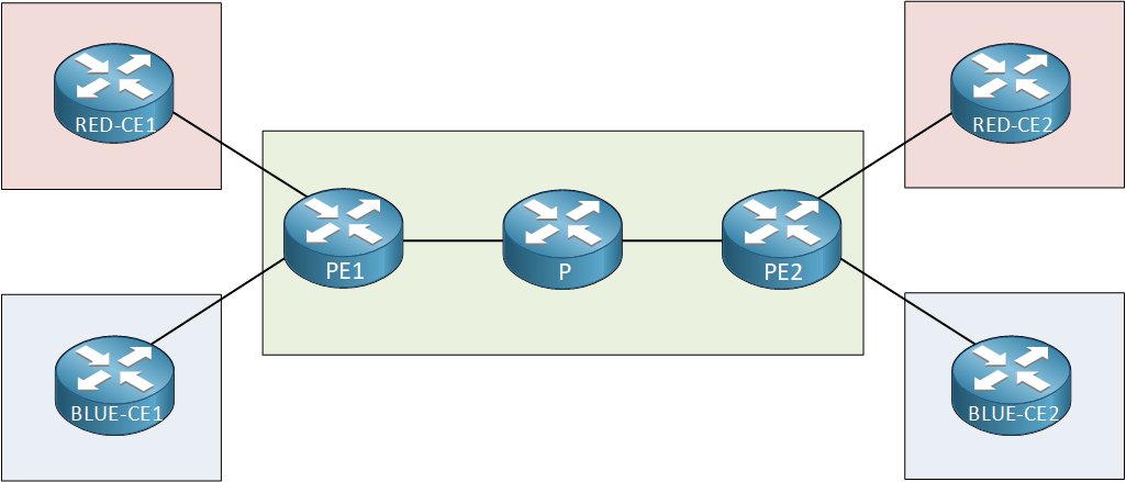
In the topology above, we have a simple MPLS VPN PE-CE topology from a provider that has two customers:
- Customer Red
- Customer Blue
Each customer has two sites. On our PE routers, we use the following configuration for our VRFs:
PE1#show run | begin ip vrf
ip vrf BLUE
 rd 2:2
 route-target export 2:2
 route-target import 2:2
!
ip vrf RED
 rd 1:1
 route-target export 1:1
route-target import 1:1PE2#show run | begin ip vrf
ip vrf BLUE
rd 2:2
route-target export 2:2
route-target import 2:2
!
ip vrf RED
rd 1:1
route-target export 1:1
route-target import 1:1Here’s what you see above:
- VRF RED uses route-target 1:1 to import and export its routes.
- VRF BLUE uses route-target 2:2 to import and export its routes.
With the configuration above, both customers are only able to communicate with their own sites. It’s impossible to send traffic from RED to BLUE or vice versa. This is what we call an MPLS intranet VPN.
Does this mean it’s impossible for customers RED and BLUE to communicate with each other at all?
This is no problem at all…the only thing we have to do is leak some routes from one VRF to another. This allows the different sites to learn about each others’ routes and they will be able to communicate with each other. This is called an MPLS VPN Extranet (Route Leaking).
Configuration
Let’s see how this works. To demonstrate this, I will use the topology I just showed you and we will leak some routes between customer site RED-CE1 and BLUE-CE2. Here it is:
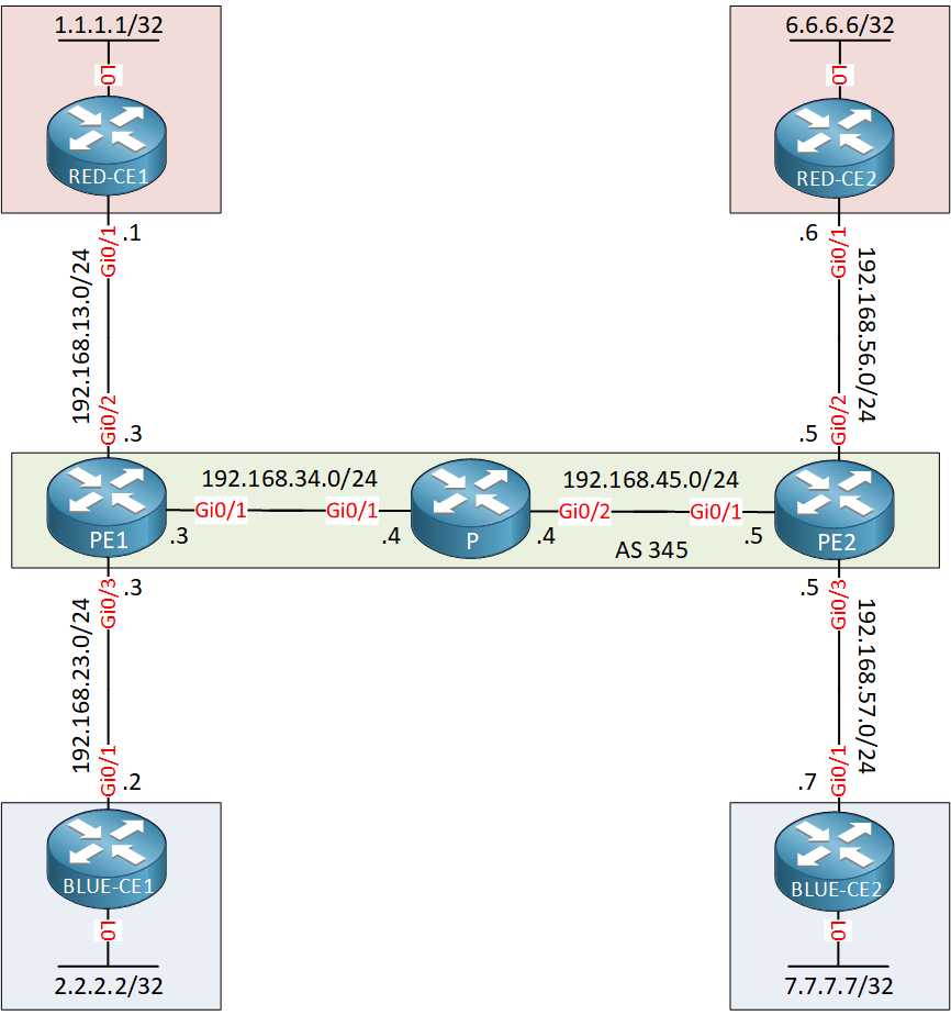
This is a basic MPLS VPN PE CE setup with two VRFs. We use OSPF as the PE-CE routing protocol.
Configurations
Want to take a look for yourself? Here you will find the startup configuration of each device.
B-CE1
hostname BLUE-CE1
!
ip cef
!
interface Loopback0
 ip address 2.2.2.2 255.255.255.255
!
interface GigabitEthernet0/1
 ip address 192.168.23.2 255.255.255.0
!
router ospf 1
 network 2.2.2.2 0.0.0.0 area 0
 network 192.168.23.0 0.0.0.255 area 0
!
end
B-CE2
hostname BLUE-CE2
!
ip cef
!
interface Loopback0
 ip address 7.7.7.7 255.255.255.255
!
interface GigabitEthernet0/1
 ip address 192.168.57.7 255.255.255.0
!
router ospf 1
 network 7.7.7.7 0.0.0.0 area 0
 network 192.168.57.0 0.0.0.255 area 0
!
end
P
hostname P
!
ip cef
!
interface Loopback0
 ip address 4.4.4.4 255.255.255.255
!
interface GigabitEthernet0/1
 ip address 192.168.34.4 255.255.255.0
 mpls ip
!
interface GigabitEthernet0/2
 ip address 192.168.45.4 255.255.255.0
 mpls ip
!
router ospf 345
 network 4.4.4.4 0.0.0.0 area 0
 network 192.168.34.0 0.0.0.255 area 0
 network 192.168.45.0 0.0.0.255 area 0
!
end
PE1
hostname PE1
!
ip vrf BLUE
 rd 2:2
 route-target export 2:2
 route-target import 2:2
!
ip vrf RED
 rd 1:1
 route-target export 1:1
 route-target import 1:1
!
ip cef
!
interface Loopback0
 ip address 3.3.3.3 255.255.255.255
!
interface GigabitEthernet0/1
 ip address 192.168.34.3 255.255.255.0
 mpls ip
!
interface GigabitEthernet0/2
 ip vrf forwarding RED
 ip address 192.168.13.3 255.255.255.0
!
interface GigabitEthernet0/3
 ip vrf forwarding BLUE
 ip address 192.168.23.3 255.255.255.0
!
router ospf 1 vrf RED
 redistribute bgp 345 subnets
 network 192.168.13.0 0.0.0.255 area 0
!
router ospf 2 vrf BLUE
 redistribute bgp 345 subnets
 network 192.168.23.0 0.0.0.255 area 0
!
router ospf 345
 network 3.3.3.3 0.0.0.0 area 0
 network 192.168.34.0 0.0.0.255 area 0
!
router bgp 345
 bgp log-neighbor-changes
 neighbor 5.5.5.5 remote-as 345
 neighbor 5.5.5.5 update-source Loopback0
 !
 address-family ipv4
  no neighbor 5.5.5.5 activate
 exit-address-family
 !
 address-family vpnv4
  neighbor 5.5.5.5 activate
  neighbor 5.5.5.5 send-community extended
 exit-address-family
 !
 address-family ipv4 vrf BLUE
  redistribute ospf 2
 exit-address-family
 !
 address-family ipv4 vrf RED
  redistribute ospf 1
 exit-address-family
!
end
PE2
hostname PE2
!
ip vrf BLUE
 rd 2:2
 route-target export 2:2
 route-target import 2:2
!
ip vrf RED
 rd 1:1
 route-target export 1:1
 route-target import 1:1
!
ip cef
!
interface Loopback0
 ip address 5.5.5.5 255.255.255.255
!
interface GigabitEthernet0/1
 ip address 192.168.45.5 255.255.255.0
 mpls ip
!
interface GigabitEthernet0/2
 ip vrf forwarding RED
 ip address 192.168.56.5 255.255.255.0
!
interface GigabitEthernet0/3
 ip vrf forwarding BLUE
 ip address 192.168.57.5 255.255.255.0
!
router ospf 1 vrf RED
 redistribute bgp 345 subnets
 network 192.168.56.0 0.0.0.255 area 0
!
router ospf 2 vrf BLUE
 redistribute bgp 345 subnets
 network 192.168.57.0 0.0.0.255 area 0
!
router ospf 345
 network 5.5.5.5 0.0.0.0 area 0
 network 192.168.45.0 0.0.0.255 area 0
!
router bgp 345
 bgp log-neighbor-changes
 neighbor 3.3.3.3 remote-as 345
 neighbor 3.3.3.3 update-source Loopback0
 !
 address-family ipv4
  no neighbor 3.3.3.3 activate
 exit-address-family
 !
 address-family vpnv4
  neighbor 3.3.3.3 activate
  neighbor 3.3.3.3 send-community extended
 exit-address-family
 !
 address-family ipv4 vrf BLUE
  redistribute ospf 2
 exit-address-family
 !
 address-family ipv4 vrf RED
  redistribute ospf 1
 exit-address-family
!
end
R-CE1
hostname RED-CE1
!
ip cef
!
interface Loopback0
 ip address 1.1.1.1 255.255.255.255
!
interface GigabitEthernet0/1
 ip address 192.168.13.1 255.255.255.0
!
router ospf 1
 network 1.1.1.1 0.0.0.0 area 0
 network 192.168.13.0 0.0.0.255 area 0
!
end
R-CE2
hostname RED-CE2
!
ip cef
!
interface Loopback0
 ip address 6.6.6.6 255.255.255.255
!
interface GigabitEthernet0/1
 ip address 192.168.56.6 255.255.255.0
!
router ospf 1
 network 6.6.6.6 0.0.0.0 area 0
 network 192.168.56.0 0.0.0.255 area 0
!
end
Right now, we have an intranet VPN so each customer only sees their own routes. Here are customer RED’s routes:
RED-CE1#show ip route ospf

      6.0.0.0/32 is subnetted, 1 subnets
O IA     6.6.6.6 [110/3] via 192.168.13.3, 00:16:14, GigabitEthernet0/1
O IA 192.168.56.0/24 [110/2] via 192.168.13.3, 00:16:14, GigabitEthernet0/1RED-CE2#show ip route ospf
1.0.0.0/32 is subnetted, 1 subnets
O IA 1.1.1.1 [110/3] via 192.168.56.5, 00:16:37, GigabitEthernet0/1
O IA 192.168.13.0/24 [110/2] via 192.168.56.5, 00:16:37, GigabitEthernet0/1And here we have customer BLUE’s routes:
BLUE-CE1#show ip route ospf

      7.0.0.0/32 is subnetted, 1 subnets
O IA     7.7.7.7 [110/3] via 192.168.23.3, 00:16:52, GigabitEthernet0/1
O IA 192.168.57.0/24 [110/2] via 192.168.23.3, 00:16:52, GigabitEthernet0/1BLUE-CE2#show ip route ospf
2.0.0.0/32 is subnetted, 1 subnets
O IA 2.2.2.2 [110/3] via 192.168.57.5, 00:17:10, GigabitEthernet0/1
O IA 192.168.23.0/24 [110/2] via 192.168.57.5, 00:17:10, GigabitEthernet0/1If I want to let RED-CE1 and BLUE-CE2 talk with each other, I’ll have to export and import some routes. I’ll use a new route-target (1:2) for this. Let’s do this step-by-step…first, let’s export the routes from VRF RED on PE1:
Hi Rene,
If I want to Communicate RED-CE1 to BLUE-CE1 and RED-CE2 to BLUE-CE2 then have to configure like the way you described in your lesson https://networklessons.com/cisco/ccie-routing-switching-written/vrf-lite-route-leaking/ . Right ???
Br//zaman
Hi Zaman,
If you don’t use MPLS then you can use VRF lite route leaking yes. If you do use MPLS, use MPLS VPN extranet route leaking.
Rene
Hello Rene,
Can we just use the existing RT for exporting/importing vrf routes ? Would this config work?
Hi Ray,
Yes, that would work just fine.
Rene
Why are the OSPF routes showing as IA route when all domain ID and area seems to be the same for the same customer?