Lesson Contents
NTP (Network Time Protocol) is used to allow network devices to synchronize their clocks with a central source clock. For network devices like routers, switches, or firewalls this is very important because we want to make sure that logging information and timestamps have the accurate time and date. If you ever have network issues or get hacked, you want to know exactly what and when it happened.
Normally a router or switch will run in NTP client mode, which means that it will adjust its clock based on the time of an NTP server. Basically the NTP protocol describes the algorithm that the NTP clients use to synchronize their clocks with the NTP server and the packets that are used between them.
A good example of a NTP server is ntp.pool.org. This is a cluster of NTP servers that many servers and network devices use to synchronize their clocks.
NTP uses a concept called “stratum” that defines how many NTP hops away a device is from an authoritative time source. For example, a device with stratum 1 is a very accurate device and might have an atomic clock attached to it. Another NTP server using this stratum 1 server to sync its own time would be a stratum two device because it’s one NTP hop further away from the source. When you configure multiple NTP servers, the client will prefer the NTP server with the lowest stratum value.
Cisco routers and switches can use three different NTP modes:
- NTP client mode.
- NTP server mode.
- NTP symmetric active mode.
The symmetric active mode is used between NTP devices to synchronize with each other, it’s used as a backup mechanism when they are unable to reach the (external) NTP server.
In the remainder of this lesson, I will demonstrate how to configure NTP on a Cisco router and switches.
Configuration
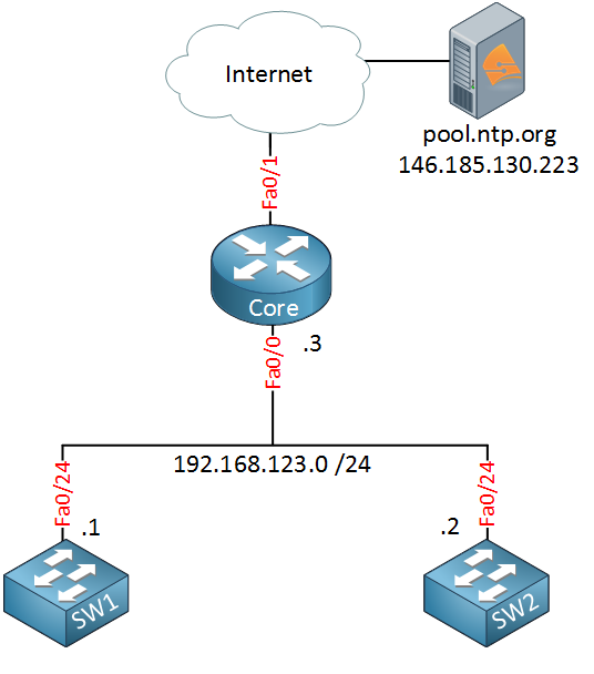
This is the topology I will use:

The router on the top is called “CoreRouter” and it’s the edge of my network. It is connected to the Internet and will use one of the NTP servers from pool.ntp.org to synchronize its clock. The network also has two internal switches that require synchronized clocks. Both switches will become NTP clients of the CoreRouter, thus making the CoreRouter an NTP server.
Router configuration
First, we will configure the CoreRouter on top. I will use pool.ntp.org as the external NTP server for this example. We need to make sure that the router can resolve hostnames:
CoreRouter(config)#ip name-server 8.8.8.8I will use Google DNS for this. Our next step is to configure the NTP server:
CoreRouter(config)#ntp server pool.ntp.orgThat was easy enough, just one command and we will synchronize our clock with the public server. We can verify our work like this:
CoreRouter#show ntp associations

  address         ref clock       st   when   poll reach  delay  offset   disp
 ~146.185.130.223 .INIT.          16      -     64     0  0.000   0.000 16000.
 * sys.peer, # selected, + candidate, - outlyer, x falseticker, ~ configured
Above we see the show ntp associations command that tells us if our clock is synchronized or not. The ~ in front of the IP address tells us that we configured this server but we are not synchronized yet. You can see this because there is no * in front of the IP address, and the “st” field (stratum) is currently 16.
There is one more command that gives us more information about the NTP configuration:
CoreRouter#show ntp status
Clock is unsynchronized, stratum 16, no reference clock
nominal freq is 250.0000 Hz, actual freq is 250.0000 Hz, precision is 2**24
reference time is 00000000.00000000 (00:00:00.000 UTC Mon Jan 1 1900)
clock offset is 0.0000 msec, root delay is 0.00 msec
root dispersion is 0.16 msec, peer dispersion is 0.00 msec
loopfilter state is 'FSET' (Drift set from file), drift is 0.000000000 s/s
system poll interval is 64, never updated.
The router tells us that we are unsynchronized and that there is no reference clock…we will wait a couple of minutes and take a look at these commands again:
CoreRouter#show ntp associations

  address         ref clock       st   when   poll reach  delay  offset   disp
*~146.185.130.223 193.79.237.14    2     26     64     1 10.857  -5.595 7937.5
 * sys.peer, # selected, + candidate, - outlyer, x falseticker, ~ configured
A few minutes later the output has changed. The * in front of the IP address tells us that we have synchronized and the stratum is 2…that means that this NTP server is pretty close to a reliable time source. The “poll” field tells us we will try synchronizing the time every 64 seconds. Let’s check the other command that we just saw:
CoreRouter#show ntp status
Clock is synchronized, stratum 3, reference is 146.185.130.22
nominal freq is 250.0000 Hz, actual freq is 250.0000 Hz, precision is 2**24
reference time is D76513B4.66A4CDA6 (12:40:20.400 UTC Mon Jul 7 2014)
clock offset is -5.5952 msec, root delay is 13.58 msec
root dispersion is 7966.62 msec, peer dispersion is 7937.50 msec
loopfilter state is 'CTRL' (Normal Controlled Loop), drift is -0.000000018 s/s
system poll interval is 64, last update was 43 sec ago.
Our clock has been synchronized, and our own stratum is 3, that makes sense since the public stratum server has a stratum of 2 and we are one “hop” away from it.
Cisco routers have two different clocks; they have a software clock and a hardware clock, and they operate separately from each other. Here’s how to see both clocks:
CoreRouter#show clock
12:41:25.197 UTC Mon Jul 7 2014CoreRouter#show calendar
12:43:24 UTC Mon Jul 7 2014The show clock command shows me the software clock, while the show calendar command gives me the hardware clock. The two clocks are not in sync, so this is something we should fix. You can do it like this:
CoreRouter#(config)ntp update-calendarThe ntp update-calendar command will update the hardware clock with the time of the software clock. Here’s the result:
CoreRouter#show clock
12:42:31.853 UTC Mon Jul 7 2014CoreRouter#show calendar
12:42:30 UTC Mon Jul 7 2014That’s all I wanted to configure on the CoreRouter for now. We still have to configure two switches to synchronize their clocks.
Switch Configuration
The two switches will be configured to use the CoreRouter as the NTP server, and I will also configure them to synchronize their clocks with each other. Let’s configure them to use the CoreRouter first:
SW1(config)#ntp server 192.168.123.3Once again, it might take a few minutes to synchronize, but this is what you will see:
SW1#show ntp associations

      address         ref clock     st  when  poll reach  delay  offset    disp
*~192.168.123.3    146.185.130.223   3    21    64    1     2.5    1.02  15875.
* master (synced), # master (unsynced), + selected, - candidate, ~ configuredSW1#show ntp status
Clock is synchronized, stratum 4, reference is 192.168.123.3
nominal freq is 119.2092 Hz, actual freq is 119.2089 Hz, precision is 2**18
reference time is D765271D.D6021302 (14:03:09.835 UTC Mon Jul 7 2014)
clock offset is 1.0229 msec, root delay is 14.31 msec
root dispersion is 16036.00 msec, peer dispersion is 15875.02 msecThe clock of SW1 has been synchronized, and its stratum is 4. This makes sense since it’s one “hop” further away from its NTP server (CoreRouter). Let’s do the same for SW2:
SW2(config)#ntp server 192.168.123.3Let’s be patient for a few more minutes, and this is what we’ll get:
SW2#show ntp associations

      address         ref clock     st  when  poll reach  delay  offset    disp
*~192.168.123.3    146.185.130.223   3    17    64   37     3.4    1.89   875.8
* master (synced), # master (unsynced), + selected, - candidate, ~ configuredSW2#show ntp status
Clock is synchronized, stratum 4, reference is 192.168.123.3
nominal freq is 119.2092 Hz, actual freq is 119.2084 Hz, precision is 2**18
reference time is D765274D.D51A0546 (14:03:57.832 UTC Mon Jul 7 2014)
clock offset is 1.8875 msec, root delay is 15.18 msec
root dispersion is 1038.39 msec, peer dispersion is 875.84 msecSW1 and SW2 are now using CoreRouter to synchronize their clocks. Let’s also configure them to use each other for synchronization. This is the symmetric active mode I mentioned before, basically, the two switches will “help” each other to synchronize…this might be useful in case the CoreRouter fails someday:
SW1(config)#ntp peer 192.168.123.2SW2(config)#ntp peer 192.168.123.1After waiting a few minutes, you’ll see that SW1 and SW2 have synchronized with each other:
SW1#show ntp associations

      address         ref clock     st  when  poll reach  delay  offset    disp
*~192.168.123.3    146.185.130.223   3    59    64   37     3.0   -0.74   877.4
+~192.168.123.2    192.168.123.3     4    50   128  376     2.2   -2.04     1.3
* master (synced), # master (unsynced), + selected, - candidate, ~ configuredSW2#show ntp associations
address ref clock st when poll reach delay offset disp
*~192.168.123.3 146.185.130.223 3 45 128 377 2.9 1.95 1.0
~192.168.123.1 192.168.123.3 4 67 1024 376 1.8 2.40 1.4
* master (synced), # master (unsynced), + selected, - candidate, ~ configuredGreat, everything is now in sync.
Configurations
Want to take a look for yourself? Here, you will find the final configuration of each device.
CoreRouter
hostname CoreRouter
!
interface FastEthernet0/0
 ip address 192.168.123.3 255.255.255.0
!
ip name-server 8.8.8.8
!
ntp server pool.ntp.org
ntp update-calendar
!
end
SW1
hostname SW1
!
interface FastEthernet0/24
 ip address 192.168.123.1 255.255.255.0
!
ntp server 192.168.123.3
ntp peer 192.168.123.2
!
end
SW2
hostname SW2
!
interface FastEthernet0/24
 ip address 192.168.123.2 255.255.255.0
!
ntp server 192.168.123.3
ntp peer 192.168.123.1
!
end
Are we done? Not quite yet…there are a few more things we can do with NTP. The CoreRouter and the two switches use unicast (UDP port 123) for synchronization, but you can also use multicast or broadcast. Let me give you an example…
Multicast and Broadcast
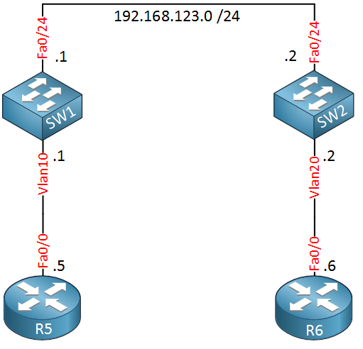
If you have more than 20 network devices or a router that has limited system memory or CPU resources, you might want to consider using NTP broadcast or multicast as it requires fewer resources. We can enable multicast or broadcast on the interface level. To demonstrate this, I will add two routers below SW1 and SW2 that will synchronize themselves using multicast or broadcast. This is what it looks like:

I’ll configure SW1 to use multicast address 239.1.1.1, and SW2 will send NTP updates through broadcast:


Excellent!
It looks like your material is Clear,Concise,to the point yet Covering every single necessary field…
Are you going to publish any book on Ccie r&s V5 Lab exam in near future (May be 8-12 month)?
Any technology specific books COVERING ANY perticular technology in details?
I love your Blog post .
Hi Subhajit Paul,
Thanks Right now I’m working on a “How to Master CCIE R&S Written” for the V5 exam and I also have plans for a BGP, OSPF, Multicast and MPLS book. I hope to have the CCIE book done in 2-3 months from now
Rene
hi Rene,
Thanks a lot for the Amazing tutorial of the NTP .. i really enjoy reading it.
i have question
i am studying CCIEv5 so is this information covering the topic of NTP inside the CCIEv5 ? or i need to read more ?
6.3.b Implement and troubleshoot network time protocol
6.3.b (i) NTP master, client, version 3, version 4
6.3.b (ii) NTP Authentication
Best Regards
Hi Sensie,
This covers most of the stuff you’ll need to know for CCIE but I would also recommend to browse through the DocCD. There are some nice NTP tricks that you might encounter in the lab…
Rene