Lesson Contents
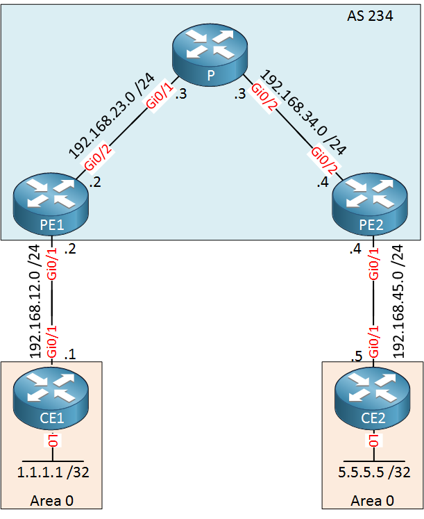
OSPF Sham Links are required when you try to use a backdoor link between two CE routers in an MPLS VPN PE CE scenario where you use OSPF as the PE-CE routing protocol. This is best explained with an example, take a look at the following topology:

Above we have an MPLS VPN topology where we use OSPF as the PE-CE routing protocol. CE1 and CE2 each have a loopback interface that is advertised in OSPF area 0. Right now, the MPLS backbone is the only way for the CE routers to reach each other.
Configurations
Want to take a look for yourself? Here you will find the startup configuration of each device.
CE1
hostname CE1
!
ip cef
!
interface Loopback0
 ip address 1.1.1.1 255.255.255.255
!
interface GigabitEthernet0/1
 ip address 192.168.12.1 255.255.255.0
!
interface GigabitEthernet0/2
 no ip address
!
router ospf 1
 network 1.1.1.1 0.0.0.0 area 0
 network 192.168.12.0 0.0.0.255 area 0
!
end
CE2
hostname CE2
!
ip cef
!
interface Loopback0
 ip address 5.5.5.5 255.255.255.255
!
interface GigabitEthernet0/1
 ip address 192.168.45.5 255.255.255.0
!
interface GigabitEthernet0/2
 no ip address
!
router ospf 1
 network 5.5.5.5 0.0.0.0 area 0
 network 192.168.45.0 0.0.0.255 area 0
!
end
P
hostname P
!
ip cef
!
interface Loopback0
 ip address 3.3.3.3 255.255.255.255
!
interface GigabitEthernet0/1
 ip address 192.168.23.3 255.255.255.0
 mpls ip
!
interface GigabitEthernet0/2
 ip address 192.168.34.3 255.255.255.0
 mpls ip
!
router ospf 1
 network 3.3.3.3 0.0.0.0 area 0
 network 192.168.23.0 0.0.0.255 area 0
 network 192.168.34.0 0.0.0.255 area 0
!
end
PE1
hostname PE1
!
ip vrf CUSTOMER
 rd 1:1
 route-target export 1:1
 route-target import 1:1
!
ip cef
!
interface Loopback0
 ip address 2.2.2.2 255.255.255.255
!
interface GigabitEthernet0/1
 ip vrf forwarding CUSTOMER
 ip address 192.168.12.2 255.255.255.0
!
interface GigabitEthernet0/2
 ip address 192.168.23.2 255.255.255.0
!
router ospf 2 vrf CUSTOMER
 redistribute bgp 234 subnets
 network 192.168.12.0 0.0.0.255 area 0
!
router ospf 1
 mpls ldp autoconfig
 network 2.2.2.2 0.0.0.0 area 0
 network 192.168.23.0 0.0.0.255 area 0
!
router bgp 234
 bgp log-neighbor-changes
 neighbor 4.4.4.4 remote-as 234
 neighbor 4.4.4.4 update-source Loopback0
 !
 address-family ipv4
  no neighbor 4.4.4.4 activate
 exit-address-family
 !
 address-family vpnv4
  neighbor 4.4.4.4 activate
  neighbor 4.4.4.4 send-community extended
 exit-address-family
 !
 address-family ipv4 vrf CUSTOMER
  redistribute ospf 2
 exit-address-family
!
end
PE2
hostname PE2
!
ip vrf CUSTOMER
 rd 1:1
 route-target export 1:1
 route-target import 1:1
!
ip cef
!
interface Loopback0
 ip address 4.4.4.4 255.255.255.255
!
interface GigabitEthernet0/1
 ip vrf forwarding CUSTOMER
 ip address 192.168.45.4 255.255.255.0
!
interface GigabitEthernet0/2
 ip address 192.168.34.4 255.255.255.0
!
router ospf 2 vrf CUSTOMER
 redistribute bgp 234 subnets
 network 192.168.45.0 0.0.0.255 area 0
!
router ospf 1
 mpls ldp autoconfig
 network 4.4.4.4 0.0.0.0 area 0
 network 192.168.34.0 0.0.0.255 area 0
!
router bgp 234
 bgp log-neighbor-changes
 neighbor 2.2.2.2 remote-as 234
 neighbor 2.2.2.2 update-source Loopback0
 !
 address-family ipv4
  no neighbor 2.2.2.2 activate
 exit-address-family
 !
 address-family vpnv4
  neighbor 2.2.2.2 activate
  neighbor 2.2.2.2 send-community extended
 exit-address-family
 !
 address-family ipv4 vrf CUSTOMER
  redistribute ospf 2
 exit-address-family
!
end
Let’s take a look at the routing tables of our CE routers:
CE1#show ip route ospf

      5.0.0.0/32 is subnetted, 1 subnets
O IA     5.5.5.5 [110/3] via 192.168.12.2, 00:09:22, GigabitEthernet0/1
O IA 192.168.45.0/24 [110/2] via 192.168.12.2, 00:09:22, GigabitEthernet0/1CE2#show ip route ospf
1.0.0.0/32 is subnetted, 1 subnets
O IA 1.1.1.1 [110/3] via 192.168.45.4, 00:09:36, GigabitEthernet0/1
O IA 192.168.12.0/24 [110/2] via 192.168.45.4, 00:09:36, GigabitEthernet0/1The CE routers see each other’s loopback interfaces as an inter-area route through the OSPF “super backbone”. Let’s try a traceroute just to be sure that our CE routers can reach each other:
CE1#traceroute 5.5.5.5 source 1.1.1.1
Type escape sequence to abort.
Tracing the route to 5.5.5.5
VRF info: (vrf in name/id, vrf out name/id)
  1 192.168.12.2 5 msec 7 msec 5 msec
  2 192.168.23.3 [MPLS: Labels 17/19 Exp 0] 9 msec 11 msec 9 msec
  3 192.168.45.4 [MPLS: Label 19 Exp 0] 9 msec 12 msec 10 msec
  4 192.168.45.5 9 msec 10 msec *
Configuration
Backdoor Link
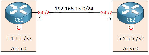
Time to mess things up. Let’s add a backdoor link between CE1 and CE2. This could be a backup link that you want to use in case the MPLS VPN provider has issues:

Let’s enable OSPF on this interface and advertise it in area 0:
CE1(config)#router ospf 1
CE1(config-router)#network 192.168.15.0 0.0.0.255 area 0CE2(config)#router ospf 1
CE2(config-router)#network 192.168.15.0 0.0.0.255 area 0The total cost through the MPLS VPN network is 4. Let’s increase the metric for our backdoor link to 100:
CE1 & CE2
(config)#interface GigabitEthernet 0/2
(config-if)#ip ospf cost 100
Let’s see which interface our CE routers now want to use:
CE1#show ip route ospf

      5.0.0.0/32 is subnetted, 1 subnets
O        5.5.5.5 [110/101] via 192.168.15.5, 00:00:22, GigabitEthernet0/2
O 192.168.45.0/24 [110/101] via 192.168.15.5, 00:00:22, GigabitEthernet0/2CE2#show ip route ospf
1.0.0.0/32 is subnetted, 1 subnets
O 1.1.1.1 [110/101] via 192.168.15.1, 00:00:27, GigabitEthernet0/2
O 192.168.12.0/24 [110/101] via 192.168.15.1, 00:00:27, GigabitEthernet0/2Despite the higher cost, CE1 and CE2 prefer the backdoor link. This is because OSPF always prefers intra-area routes over inter-area routes.
CE1#traceroute 5.5.5.5 source 1.1.1.1
Type escape sequence to abort.
Tracing the route to 5.5.5.5
VRF info: (vrf in name/id, vrf out name/id)
  1 192.168.15.5 7 msec 4 msec *
OSPF Sham Link
The only way to fix this is to advertise the routes that are learned through the MPLS VPN network as intra-area routes. We can do this with the OSPF sham link. The sham link is a logical link, similar to a virtual link. It allows you to create a point-to-point connection between the two PE routers. The PE routers are then able to flood LSAs across the MPLS VPN backbone. You don’t have to configure anything on the CE routers.
The sham link is established between two IP addresses that have to be in the VRF of the customer. To achieve this, we will create a new loopback interface on each PE router which is advertised in BGP:
- PE1: 22.22.22.22/32
- PE2: 44.44.44.44/32
Let’s start with PE1:
PE1(config)#interface loopback 1
PE1(config-if)#ip vrf forwarding CUSTOMER
PE1(config-if)#ip address 22.22.22.22 255.255.255.255
Let’s advertise this IP address in BGP:


Hi Rene,
So, the sham link is required only for MPLS VPN scenario ?? Thx
br//zaman
That’s correct. MPLS VPN PE-CE with OSPF as the routing protocol between PE/CE.
Hi Rene,
In order for redistribution other routing protocols into OSPF on CE works properly, we have to setup Sham Link. Is that correct?
Looks like LSA type 5 & 7 are not exchanged cross MPLS backbone? Correct me if I’m wrong. Because I have tried redistribution other routing protocols into OSPF on CE without Sham Link and result is PE which connected directly with CE got the routes but other PEs didn’t got it.
Thanks,
Minh
Hello Minh,
Redistributed routes in OSPF on a CE router is no problem. You only need a sham link when you have a backdoor link in between your CE routers.
By default, OSPF external routes don’t get redistributed into BGP but you can change that. Here’s a quick example:
... Continue reading in our forumThank you, Rene.
Rgds,
Minh