

Lesson Contents
IPv6 ND has no built-in authentication. Any device can send Neighbor Advertisements (NA) claiming any IPv6 address. Luckily, there is something we can do about this.
IPv6 Device Tracking is part of the IPv6 First Hop Security feature set and the modern name for what used to be configured with the legacy IPv6 first-hop security commands such as ipv6 nd inspection and ipv6 snooping. On current Cisco IOS-XE releases, those old commands are deprecated and are now under a single SISF (Switch Integrated Security Features) framework that you configure with device-tracking commands.
If you try the old command on a modern image, the switch tells you so directly:
SW1(config)#ipv6 nd inspection policy TEST
WARNING: ipv6 nd inspection policy is deprecated, use device-tracking policy
Device tracking builds a binding table of IP-to-MAC-to-interface entries, learned from Neighbor Discovery (NS/NA), DHCP, ARP, and (optionally) data traffic. The switch then validates future ND messages against this table. When the IPv6/MAC/interface combination doesn’t match a more trusted entry, the message is dropped. Just like ND inspection, this protects the control plane (NS/NA messages); it is also the foundation for other features such as IPv6 Source Guard and RA Guard, which all use the same binding table.
In this lesson, I’ll show you how to configure device tracking.
Key Takeaways
- IPv6 device tracking uses a named policy created with
device-tracking policywhich is then attached to interfaces or VLANs. - The security-level option inside a policy has three modes:
- glean (passive learning only)
- inspect (learn and validate but do not drop)
- guard (learn, validate, and drop unauthorized messages)
- The device-role option distinguishes between node ports (which drop Router Advertisements) and router ports (which allow them), so it is important to set the correct role for each interface.
- You can use
show device-tracking policyto confirm policy settings and which interfaces it is applied to, andshow device-tracking databaseto inspect the live IP-to-MAC-to-interface binding table. - The binding table operates on a first-come, first-served basis: once a legitimate device’s binding is recorded, a spoofed ND message arriving on a different port is dropped because a more trusted entry already exists.
- Static bindings can be added with d
evice-tracking binding vlanand receive a higher preference level (0100) than dynamic entries (0005), allowing you to pin a specific IP address to a specific port and MAC. - When tracking is enabled with a reachable-lifetime, the switch periodically sends unicast Neighbor Solicitation probes (sourced from the unspecified address ::) directly to the known MAC of each binding entry.
- SW1 uses a locally generated MAC address (not one of its physical port MACs) as the source when sending these NS probes, and devices reply with a Neighbor Advertisement to the all-nodes multicast address (ff02::1) with the Override flag set to refresh the binding table.
Configuration
We’ll use the following topology:
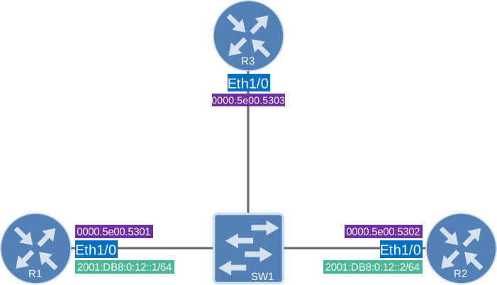
Here’s what we have:
- R1 and R2 are routers with a static IPv6 address.
- R3 is an attacker that will spoof R2’s IPv6 address.
- SW1 is where we configure device tracking.
I’m using routers but we don’t do any routing. I’m using them as if they are host devices.
R1, R2, and R3 each have a statically configured MAC address on their link interfaces, making their link-local addresses predictable.
Configurations
Want to take a look for yourself? Here you will find the startup configuration of each device.
R1
hostname R1
!
interface GigabitEthernet2
 no ip address
 mac-address 0000.5e00.5301
 ipv6 address 2001:DB8:0:12::1/64
 ipv6 enable
!
end
R2
hostname R2
!
interface GigabitEthernet2
 no ip address
 mac-address 0000.5e00.5302
 ipv6 address 2001:DB8:0:12::2/64
 ipv6 enable
!
end
R3
hostname R3
!
interface GigabitEthernet2
 no ip address
 mac-address 0000.5e00.5303
 ipv6 enable
 ipv6 nd dad attempts 0
!
end
SW1
hostname SW1
!
interface Ethernet0/1
!
interface Ethernet0/2
!
interface Ethernet0/3
!
end
Device Tracking Policy
Unlike the old single-line ipv6 nd inspection command, the modern approach is always policy-based. You create a named device-tracking policy, then attach it to interfaces or VLANs. Let’s look at the options inside a policy:
SW1(config)#device-tracking policy MY_POLICY
SW1(config-device-tracking)#?
device-tracking policy configuration mode:
  data-glean            binding recovery by data traffic source address gleaning
  default               Set a command to its defaults
  destination-glean     binding recovery by data traffic destination address gleaning
  device-role           Sets the role of the device attached to the port
  distribution-switch   Distribution switch to sync with
  exit                  Exit from device-tracking policy configuration mode
  limit                 Specifies a limit
  medium-type-wireless  Force medium type to wireless
  no                    Negate a command or set its defaults
  prefix-glean          Glean prefixes in RA and DHCP-PD traffic
  protocol              Sets the protocol to glean (default all)
  security-level        setup security level
  tracking              Override default tracking behavior
  trusted-port          setup trusted port
  vpc                   setup vpc port
The most important option is security-level, which replaces the old “inspection vs. snooping” distinction:
SW1(config-device-tracking)#security-level ?
  glean    glean addresses passively
  guard    inspect and drop un-authorized messages (default)
  inspect  glean and Validate message
There are three options. Let me explain:
glean: Passively learns bindings. This is the old “snooping” behavior.inspect: This is glean and validate, but it doesn’t drop anything.guard: This is glean and validate, and it drops unauthorized messages. This is the default and is what gives us the protection the oldipv6 nd inspectionprovided.
The device-role option tells the switch what is attached to the port:
SW1(config-device-tracking)#device-role ?
  node    Attached device is a node (default)
  router  Attached device is a router
  switch  Attached device is a switch
Let’s build a policy. We set security-level guard, limit the number of addresses per port to two (one link-local and one global unicast for a typical host), and enable tracking with a short reachable-lifetime so we can see the probes:
SW1(config)#device-tracking policy MY_POLICY
SW1(config-device-tracking)#security-level guard
SW1(config-device-tracking)#device-role node
SW1(config-device-tracking)#limit address-count 2
SW1(config-device-tracking)#tracking enable reachable-lifetime 10
SW1(config-device-tracking)#exit
Now attach the policy to the access ports:
SW1(config)#interface range Ethernet0/1 - 3
SW1(config-if-range)#device-tracking attach-policy MY_POLICYdevice-role router. Ports with the node role drop router advertisements while router role ports allow them.Verification
Let’s verify our work. We can check the policy and where it’s applied:
SW1#show device-tracking policy MY_POLICY
Device-tracking policy MY_POLICY configuration:
  security-level guard
  device-role node
  gleaning from Neighbor Discovery
  gleaning from DHCP6
  gleaning from ARP
  gleaning from DHCP4
  NOT gleaning from protocol unkn
  limit address-count 2
  tracking enable reachable-lifetime 10
Policy MY_POLICY is applied on the following targets:
Target               Type  Policy               Feature        Target range
Et0/1                PORT  MY_POLICY            Device-tracking vlan all
Et0/2                PORT  MY_POLICY            Device-tracking vlan all
Et0/3                PORT  MY_POLICY            Device-tracking vlan all
This tells us what is in the policy and on which interfaces it is applied.
Dynamic Binding
To see if it works, we have to generate some traffic. We’ll do this by sending a ping from R1 to R2. This will generate some Neighbor Discovery (ND) traffic:
R1#ping 2001:DB8:0:12::2 repeat 5
Type escape sequence to abort.
Sending 5, 100-byte ICMP Echos to 2001:DB8:0:12::2, timeout is 2 seconds:
!!!!!
Success rate is 100 percent (5/5), round-trip min/avg/max = 1/1/1 ms
The switch populates its binding table:
SW1#show device-tracking database
Binding Table has 4 entries, 4 dynamic (limit 200000)
Codes: L - Local, S - Static, ND - Neighbor Discovery, ARP - Address Resolution Protocol, DH4 - IPv4 DHCP, DH6 - IPv6 DHCP, PKT - Other Packet, API - API created
Preflevel flags (prlvl):
0001:MAC and LLA match     0002:Orig trunk            0004:Orig access
0008:Orig trusted trunk    0010:Orig trusted access   0020:DHCP assigned
0040:Cga authenticated     0080:Cert authenticated    0100:Statically assigned

    Network Layer Address           Link Layer Address  Interface  vlan/bd  prlvl  age  state      Time left
ND  FE80::200:5EFF:FE00:5302         0000.5e00.5302      Et0/2      1        0005   4s   REACHABLE  7 s
ND  FE80::200:5EFF:FE00:5301         0000.5e00.5301      Et0/1      1        0005   1s   REACHABLE  9 s
ND  2001:DB8:0:12::2                 0000.5e00.5302      Et0/2      1        0005   6s   REACHABLE  4 s
ND  2001:DB8:0:12::1                 0000.5e00.5301      Et0/1      1        0005   5s   REACHABLE  5 s
The entries are learned via ND, each mapped to the correct interface, VLAN, and MAC. Note that the MAC addresses now match our static configuration (0000.5e00.5301 for R1, 0000.5e00.5302 for R2) instead of the auto-generated ones. The prlvl (preference level) column shows 0005, which means it was learned dynamically on an access port.
The binding table is there. Now let’s have R3 spoof R2’s link-local address. We disable DAD and copy R2’s link-local address onto R3:
R3(config)#interface GigabitEthernet2
R3(config-if)#ipv6 nd dad attempts 0
R3(config-if)#ipv6 address FE80::200:5EFF:FE00:5302 link-local
Now generate an ND message from R3 using this spoofed source, aimed at R1:
R3#ping FE80::200:5EFF:FE00:5301 source GigabitEthernet2 repeat 3
Output Interface: GigabitEthernet 2
Type escape sequence to abort.
Sending 3, 100-byte ICMP Echos to FE80::200:5EFF:FE00:5301, timeout is 2 seconds:
Packet sent with a source address of FE80::200:5EFF:FE00:5302%GigabitEthernet2
...
Success rate is 0 percent (0/3)
The ping fails completely. When R3 tries to use that spoofed address, SW1’s guard policy blocks it. Because we already have a more trusted entry from R2, the switch drops R3’s ND messages. We can see this with the per-interface counters:
SW1#show device-tracking counters interface Ethernet0/3
Received messages on Et0/3:
Protocol        Protocol message
NDP             RA[3] NS[6] NA[1]
...
Dropped messages on Et0/3:
Feature             Protocol Msg [Total dropped]
Device-tracking:    NDP      RA  [3]
                    reason:  Packet not authorized on port [3]

                             NS  [6]
                    reason:  More trusted entry exists [4]
                    reason:  Packet accepted but not forwarded [2]

                             NA  [1]
                    reason:  More trusted entry exists [1]
The reason “More trusted entry exists” says enough. The binding table works on a “first come, first served” basis: since R2’s binding already exists (learned on Et0/2), R3’s spoofed messages arriving on Et0/3 are dropped. The binding table itself confirms nothing from R3 got in:
SW1#show device-tracking database
    Network Layer Address                    Link Layer Address     Interface  vlan/bd    prlvl      age        state      Time left
ND  FE80::200:5EFF:FE00:5302                 0000.5e00.5302         Et0/2      1          0005       6s         REACHABLE  3 s
ND  FE80::200:5EFF:FE00:5301                 0000.5e00.5301         Et0/1      1          0005       2s         REACHABLE  7 s
ND  2001:DB8:0:12::2                         0000.5e00.5302         Et0/2      1          0005       7s         REACHABLE  3 s
ND  2001:DB8:0:12::1                         0000.5e00.5301         Et0/1      1          0005       5s         REACHABLE  4 s
Let’s clean up the spoofed address on R3:
R3(config)#interface GigabitEthernet2
R3(config-if)#no ipv6 address FE80::200:5EFF:FE00:5302 link-local
Static Binding
Just like with ND inspection, you can override the dynamic learning with a static binding, which has the highest preference level. Here’s how to do it, pointing R2’s global address at R3’s port and MAC instead:
SW1(config)#device-tracking binding vlan 1 2001:DB8:0:12::2 interface Ethernet0/3 0000.5e00.5303This now shows up as a static (S) entry with preference level 0100, pointing to R3’s interface and MAC:
SW1#show device-tracking database | begin Network
    Network Layer Address           Link Layer Address  Interface  vlan/bd  prlvl  age  state      Time left
ND  FE80::200:5EFF:FE00:5302         0000.5e00.5302      Et0/2      1        0005   7s   REACHABLE  3 s
ND  FE80::200:5EFF:FE00:5301         0000.5e00.5301      Et0/1      1        0005   5s   REACHABLE  5 s
S   2001:DB8:0:12::2                 0000.5e00.5303      Et0/3      1        0100   8s   REACHABLE  303 s
ND  2001:DB8:0:12::1                 0000.5e00.5301      Et0/1      1        0005   6s   REACHABLE  4 s
Because the static binding has a higher preference level than the dynamic one, the address now points to R3. Now you have seen how to do it, let’s get rid of it:
SW1(config)#no device-tracking binding vlan 1 2001:DB8:0:12::2 interface Ethernet0/3 0000.5e00.5303Packet Captures
Let’s look at some packet captures. If you want to follow along, here is the capture file:
Packet Capture: IPv6 Device Tracking SW1 Probe to R1
Because we enabled tracking enable reachable-lifetime 10, the switch periodically sends a Neighbor Solicitation (NS) to the addresses in its binding table to confirm they’re still there. This lets the switch clean up stale entries and quickly update bindings when a device moves between ports.
Here is the first packet. SW1 sends an NS probe for R1’s link-local address:
Frame 2: Packet, 78 bytes on wire (624 bits), 78 bytes captured (624 bits) on interface eth1, id 0
Ethernet II, Src: aa:bb:cc:00:04:10 (aa:bb:cc:00:04:10), Dst: ICANNIANADep_00:53:01 (00:00:5e:00:53:01)
Internet Protocol Version 6, Src: ::, Dst: ff02::1:ff00:5301
Internet Control Message Protocol v6
    Type: Neighbor Solicitation (135)
    Code: 0
    Checksum: 0x7724 [correct]
    [Checksum Status: Good]
    Reserved: 00000000
    Target Address: fe80::200:5eff:fe00:5301
This output is interesting. The source MAC address (aa:bb:cc:00:04:10) is a locally significant MAC address generated by SW1 to source these probes. It’s not one of SW1’s physical port MAC addresses. The destination MAC address is unicast (00:00:5e:00:53:01), which is R1’s real MAC address. Normally, you would expect a solicited-node multicast destination (33:33:ff:00:53:01) here. Because SW1 already has R1 in its binding table (interface and MAC are known), it sends the probe as an L2 unicast frame directly to R1 instead of flooding it as a multicast. It only needs to ask R1 specifically, not the whole segment. This is a nice optimization.
SW1 has no IPv6 address of its own, so it uses the unspecified address as the source IPv6 address for these probes. The destination IPv6 address is the solicited-node multicast address derived from the target fe80::200:5eff:fe00:5301. This is standard ND behavior.
SW1 also sends an NS probe for R1’s global address:
Frame 3: Packet, 78 bytes on wire (624 bits), 78 bytes captured (624 bits) on interface eth1, id 0
Ethernet II, Src: aa:bb:cc:00:04:10 (aa:bb:cc:00:04:10), Dst: ICANNIANADep_00:53:01 (00:00:5e:00:53:01)
Internet Protocol Version 6, Src: ::, Dst: ff02::1:ff00:1
Internet Control Message Protocol v6
    Type: Neighbor Solicitation (135)
    Code: 0
    Checksum: 0x4cdb [correct]
    [Checksum Status: Good]
    Reserved: 00000000
    Target Address: 2001:db8:0:12::1
This is the same probe mechanism as the first one, but this time SW1 is checking R1’s global unicast binding entry (2001:db8:0:12::1) instead of the link-local address. This confirms that the switch tracks and probes both entries per port. The link-local and one global address. It’s limited by the limit address-count 2 command.
R1 replies with a Neighbor Advertisement (NA) to confirm its link-local address: