Lesson Contents
In an MPLS VPN PE-CE network, some customers might require Internet access. One way to achieve this is by routing your traffic from the VRF to the global routing table and back. Another way to provide Internet access is to advertise a default route within a VRF, as we did in the MPLS VPN PE-CE OSPF default route lesson.
I’ll explain how to “leak” traffic from a VRF to the global routing table in this lesson. We’ll configure necessary static routes in the VRF and global routing table and advertise required routes through OSPF.
Let’s get started!
Configuration
Here is the topology we’ll use:
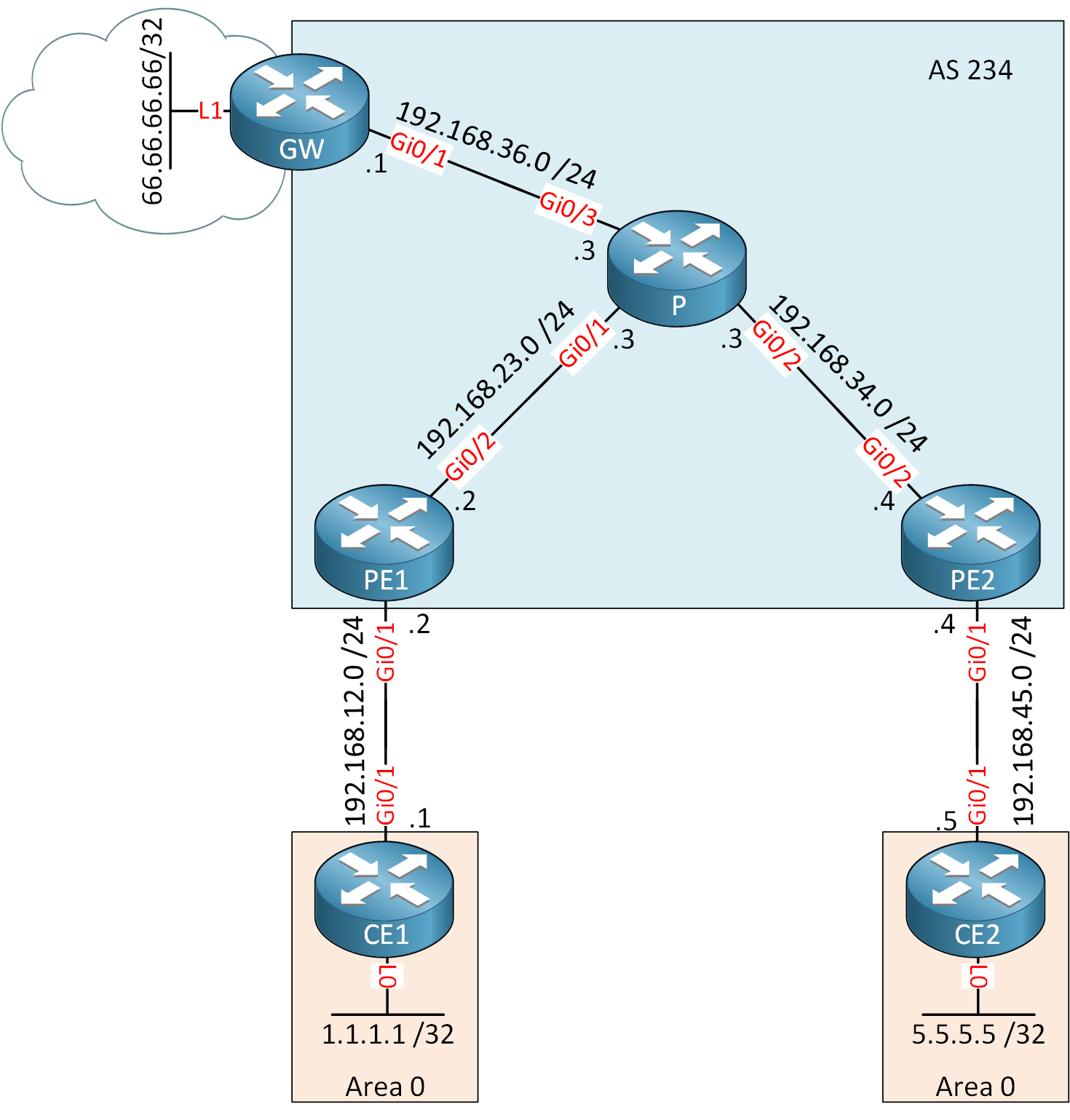
The topology is the same as the one I use in the MPLS VPN PE-CE OSPF lesson but I added a GW router that is connected to the “Internet”. The 66.66.66.66/32 address on the GW router simulates a server on the Internet.
Configurations
Want to take a look for yourself? Here you will find the startup configuration of each device.
CE1
hostname CE1
!
ip cef
!
interface Loopback0
 ip address 1.1.1.1 255.255.255.255
!
interface GigabitEthernet0/1
 ip address 192.168.12.1 255.255.255.0
!
router ospf 1
 network 1.1.1.1 0.0.0.0 area 0
 network 192.168.12.0 0.0.0.255 area 0
!
end
CE2
hostname CE2
!
ip cef
!
interface Loopback0
 ip address 5.5.5.5 255.255.255.255
!
interface GigabitEthernet0/1
 ip address 192.168.45.5 255.255.255.0
!
router ospf 1
 network 5.5.5.5 0.0.0.0 area 0
 network 192.168.45.0 0.0.0.255 area 0
!
end
GW
hostname GW
!
ip cef
!
interface Loopback0
 ip address 6.6.6.6 255.255.255.255
!
interface Loopback1
 ip address 66.66.66.66 255.255.255.255
!
interface GigabitEthernet0/1
 ip address 192.168.36.6 255.255.255.0
!
end
P
hostname P
!
ip cef
!
interface Loopback0
 ip address 3.3.3.3 255.255.255.255
!
interface GigabitEthernet0/1
 ip address 192.168.23.3 255.255.255.0
 mpls ip
!
interface GigabitEthernet0/2
 ip address 192.168.34.3 255.255.255.0
 mpls ip
!
interface GigabitEthernet0/3
 ip address 192.168.36.3 255.255.255.0
!
router ospf 1
 network 3.3.3.3 0.0.0.0 area 0
 network 192.168.23.0 0.0.0.255 area 0
 network 192.168.34.0 0.0.0.255 area 0
!
end
PE1
hostname PE1
!
ip vrf CUSTOMER
 rd 1:1
 route-target export 1:1
 route-target import 1:1
!
ip cef
!
interface Loopback0
 ip address 2.2.2.2 255.255.255.255
!
interface GigabitEthernet0/1
 ip vrf forwarding CUSTOMER
 ip address 192.168.12.2 255.255.255.0
!
interface GigabitEthernet0/2
 ip address 192.168.23.2 255.255.255.0
!
router ospf 2 vrf CUSTOMER
 redistribute bgp 234 subnets
 network 192.168.12.0 0.0.0.255 area 0
!
router ospf 1
 mpls ldp autoconfig
 network 2.2.2.2 0.0.0.0 area 0
 network 192.168.23.0 0.0.0.255 area 0
!
router bgp 234
 neighbor 4.4.4.4 remote-as 234
 neighbor 4.4.4.4 update-source Loopback0
 !
 address-family ipv4
  no neighbor 4.4.4.4 activate
 exit-address-family
 !
 address-family vpnv4
  neighbor 4.4.4.4 activate
  neighbor 4.4.4.4 send-community extended
 exit-address-family
 !
 address-family ipv4 vrf CUSTOMER
  redistribute ospf 2
 exit-address-family
!
end
PE2
hostname PE2
!
ip vrf CUSTOMER
 rd 1:1
 route-target export 1:1
 route-target import 1:1
!
ip cef
!
interface Loopback0
 ip address 4.4.4.4 255.255.255.255
!
interface GigabitEthernet0/1
 ip vrf forwarding CUSTOMER
 ip address 192.168.45.4 255.255.255.0
!
interface GigabitEthernet0/2
 ip address 192.168.34.4 255.255.255.0
!
router ospf 2 vrf CUSTOMER
 redistribute bgp 234 subnets
 network 192.168.45.0 0.0.0.255 area 0
!
router ospf 1
 mpls ldp autoconfig
 network 4.4.4.4 0.0.0.0 area 0
 network 192.168.34.0 0.0.0.255 area 0
!
router bgp 234
 neighbor 2.2.2.2 remote-as 234
 neighbor 2.2.2.2 update-source Loopback0
 !
 address-family ipv4
  no neighbor 2.2.2.2 activate
 exit-address-family
 !
 address-family vpnv4
  neighbor 2.2.2.2 activate
  neighbor 2.2.2.2 send-community extended
 exit-address-family
 !
 address-family ipv4 vrf CUSTOMER
  redistribute ospf 2
 exit-address-family
!
end
OSPF between P and GW
First, we’ll configure OSPF on the GW and P routers. I advertise a loopback interface on the GW router which we need later as the next-hop address for a static route:
GW(config)#router ospf 1
GW(config-router)#network 6.6.6.6 0.0.0.0 area 0
GW(config-router)#network 192.168.36.0 0.0.0.255 area 0P(config)#router ospf 1
P(config-router)#network 192.168.36.0 0.0.0.255 area 0From VRF to Global
Let’s focus on getting traffic from the VRF to the global routing table. We can do this by configuring a static route on the PE routers and adding the globalparameter. This tells the router that the next hop is in the global routing table, not in the VRF:
PE1 & PE2
(config)#ip route vrf CUSTOMER 0.0.0.0 0.0.0.0 6.6.6.6 global
The static route is now on the PE routers but we also need it on the CE routers. Let’s configure OSPF to advertise a default route in the VRF:
PE1 & PE2
(config)#router ospf 2 vrf CUSTOMER
(config-router)#default-information originate
OSPF will only advertise a default route when the PE routers have a default route in their routing tables. Thanks to this default route, the CE routers now know to reach unknown destinations.
From Global to VRF
Our CE routers can make it to the GW router, but we also have to think about the return traffic. The GW router somehow needs to know how it can reach 1.1.1.1 (CE1) or 5.5.5.5 (CE2). The traffic is routed in the global routing table, so we need something there.
To achieve this, I will add a static route in the global routing table on the PE routers which points to the CE routers. I will redistribute these static routes into OSPF so that the GW and P routers know how to reach these networks.
PE1
The static route that points to the VRF must point to an interface and if it’s a multi-access interface, we also have to include the next-hop IP address. This static route is in the global routing table but the next-hop IP address is in the VRF. Normally, this static route would be invalid but with MPLS VPN, this is a valid configuration. Here’s the static route:
Hi Rene, Thanks for the lesson. could you please also show global to vrf route leaking in non MPLS environment. How it works
Hello Pushpender
You can find an example of VRF route leaking in a non-MPLS environment at the following lesson:
https://networklessons.com/cisco/ccie-routing-switching-written/vrf-lite-route-leaking
I hope this has been helpful!
Laz
Hello Wuilmer
Yes, it is possible to redistribute dynamic routing protocols to redistribute routes between VRFs and the global routing table. However, in order to do so, you must be running separate instances of a routing protocol in the VRF and the global routing domain. In the lesson, the global routing domain only uses static routes. However, if you take a look at the following lesson, you will see how routes are being redistributed between the global routing domain and a VRF using dynamic routing protocols:
https://networklessons.com/mpls/mpls-layer-3-vp
... Continue reading in our forumyou need to advertise 66.66.66.66 lo0 interface on the GW router
Hello Bahri
Actually, the 66.66.66.66 network doesn’t have to be advertised. Any traffic to 66.66.66.66 will match the default route configured in the PEs. The default route will allow traffic to reach the GW device, thus reaching 66.66.66.66.
I hope this has been helpful!
Laz