Lesson Contents
Running MPLS VPN over TE tunnels is no problem, but you might run into an issue with penultimate hop popping (PHP). In this lesson, we’ll look at different scenarios, the labels we use, the possible issues you can run into, and how to fix them. Before you continue, make sure you are familiar with MPLS VPN and MPLS traffic engineering.
Configuration
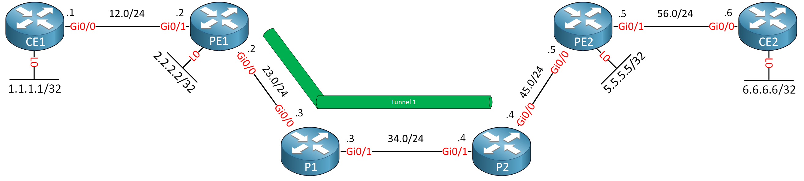
This is the topology we’ll use:
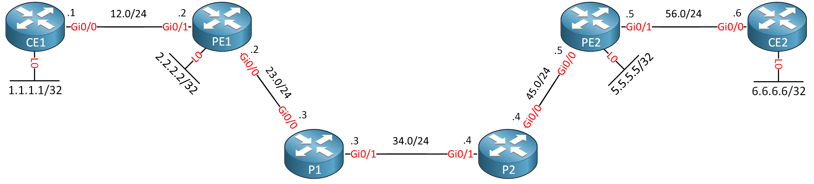
The PE and P routers are configured for MPLS TE. The CE routers are in a VRF. Make sure you are familiar with a standard MPLS TE and MPLS VPN configuration.
I use Cisco IOS Software, IOSv Software (VIOS-ADVENTERPRISEK9-M), Version 15.9(3)M6, RELEASE SOFTWARE (fc1) on all routers.
Configurations
Want to take a look for yourself? Here you will find the startup configuration of each device.
CE1
hostname CE1
!
ip cef
!
interface Loopback0
 ip address 1.1.1.1 255.255.255.255
!
interface GigabitEthernet0/0
 ip address 192.168.12.1 255.255.255.0
!
router ospf 1
 network 1.1.1.1 0.0.0.0 area 0
 network 192.168.12.0 0.0.0.255 area 0
!
end
CE2
hostname CE2
!
ip cef
!
interface Loopback0
 ip address 6.6.6.6 255.255.255.255
!
interface GigabitEthernet0/0
 ip address 192.168.56.6 255.255.255.0
!
router ospf 1
 network 6.6.6.6 0.0.0.0 area 0
 network 192.168.56.0 0.0.0.255 area 0
!
end
P1
hostname P1
!
ip cef
!
mpls traffic-eng tunnels
!
interface Loopback0
 ip address 3.3.3.3 255.255.255.255
 ip router isis
 isis circuit-type level-2-only
!
interface GigabitEthernet0/0
 ip address 192.168.23.3 255.255.255.0
 ip router isis
 mpls traffic-eng tunnels
 mpls ip
 isis circuit-type level-2-only
 ip rsvp bandwidth 1000000
!
interface GigabitEthernet0/1
 ip address 192.168.34.3 255.255.255.0
 ip router isis
 mpls traffic-eng tunnels
 mpls ip
 isis circuit-type level-2-only
 ip rsvp bandwidth 1000000
!
router isis
 mpls traffic-eng router-id Loopback0
 mpls traffic-eng level-2
 net 49.0001.0003.0003.0003.0003.00
 is-type level-2-only
 metric-style wide
!
mpls ldp router-id Loopback0 force
!
end
P2
hostname P2
!
ip cef
!
mpls traffic-eng tunnels
!
interface Loopback0
 ip address 4.4.4.4 255.255.255.255
 ip router isis
 isis circuit-type level-2-only
!
interface GigabitEthernet0/0
 ip address 192.168.45.4 255.255.255.0
 ip router isis
 mpls traffic-eng tunnels
 mpls ip
 isis circuit-type level-2-only
 ip rsvp bandwidth 1000000
!
interface GigabitEthernet0/1
 ip address 192.168.34.4 255.255.255.0
 ip router isis
 mpls traffic-eng tunnels
 mpls ip
 isis circuit-type level-2-only
 ip rsvp bandwidth 1000000
!
router isis
 mpls traffic-eng router-id Loopback0
 mpls traffic-eng level-2
 net 49.0001.0004.0004.0004.0004.00
 is-type level-2-only
 metric-style wide
!
mpls ldp router-id Loopback0 force
!
end
PE1
hostname PE1
!
ip vrf CUSTOMER
 rd 1:1
 route-target export 1:1
 route-target import 1:1
!
ip cef
!
mpls traffic-eng tunnels
mpls traffic-eng logging lsp setups
mpls traffic-eng logging lsp teardowns
mpls traffic-eng reoptimize events link-up
!
interface Loopback0
 ip address 2.2.2.2 255.255.255.255
 ip router isis
 isis circuit-type level-2-only
!
interface Tunnel1
 ip unnumbered Loopback0
 tunnel mode mpls traffic-eng
 tunnel destination 6.6.6.6
 tunnel mpls traffic-eng priority 7 7
 tunnel mpls traffic-eng bandwidth 750
 tunnel mpls traffic-eng path-option 1 dynamic
 no routing dynamic
!
interface GigabitEthernet0/0
 ip address 192.168.23.2 255.255.255.0
 ip router isis
 mpls traffic-eng tunnels
 mpls ip
 isis circuit-type level-2-only
 ip rsvp bandwidth 1000000
!
interface GigabitEthernet0/1
 ip vrf forwarding CUSTOMER
 ip address 192.168.12.2 255.255.255.0
!
router ospf 1 vrf CUSTOMER
 redistribute bgp 1 subnets
 network 192.168.12.0 0.0.0.255 area 0
!
router isis
 mpls traffic-eng router-id Loopback0
 net 49.0001.0002.0002.0002.0002.00
 is-type level-2-only
 metric-style wide
!
router bgp 1
 neighbor 5.5.5.5 remote-as 1
 neighbor 5.5.5.5 update-source Loopback0
 !
 address-family vpnv4
  neighbor 5.5.5.5 activate
  neighbor 5.5.5.5 send-community extended
 exit-address-family
 !
 address-family ipv4 vrf CUSTOMER
  redistribute ospf 1
 exit-address-family
!
mpls ldp router-id Loopback0 force
!
end
PE2
hostname PE2
!
ip vrf CUSTOMER
 rd 1:1
 route-target export 1:1
 route-target import 1:1
!
ip cef
!
mpls traffic-eng tunnels
!
interface Loopback0
 ip address 5.5.5.5 255.255.255.255
 ip router isis
 isis circuit-type level-2-only
!
interface GigabitEthernet0/0
 ip address 192.168.45.5 255.255.255.0
 ip router isis
 mpls traffic-eng tunnels
 mpls ip
 isis circuit-type level-2-only
 ip rsvp bandwidth 1000000
!
interface GigabitEthernet0/1
 ip vrf forwarding CUSTOMER
 ip address 192.168.56.5 255.255.255.0
!
router ospf 1 vrf CUSTOMER
 redistribute bgp 1 subnets
 network 192.168.56.0 0.0.0.255 area 0
!
router isis
 mpls traffic-eng router-id Loopback0
 mpls traffic-eng level-2
 net 49.0001.0005.0005.0005.0005.00
 is-type level-2-only
 metric-style wide
!
router bgp 1
 neighbor 2.2.2.2 remote-as 1
 neighbor 2.2.2.2 update-source Loopback0
 !
 address-family vpnv4
  neighbor 2.2.2.2 activate
  neighbor 2.2.2.2 send-community extended
 exit-address-family
 !
 address-family ipv4 vrf CUSTOMER
  redistribute ospf 1
 exit-address-family
!
mpls ldp router-id Loopback0 force
!
end
MPLS VPN without TE tunnel
The first example is straightforward. This is a regular MPLS VPN without any TE tunnels. We’ll start with this example to see what the labels are like.
PE1 learns VPN IPv4 CE2’s prefixes 192.168.56.0/24 and 6.6.6.6/32 through BGP that are advertised by PE2:
PE1#show ip route vrf CUSTOMER bgp

Routing Table: CUSTOMER
Codes: L - local, C - connected, S - static, R - RIP, M - mobile, B - BGP
       D - EIGRP, EX - EIGRP external, O - OSPF, IA - OSPF inter area
       N1 - OSPF NSSA external type 1, N2 - OSPF NSSA external type 2
       E1 - OSPF external type 1, E2 - OSPF external type 2
       i - IS-IS, su - IS-IS summary, L1 - IS-IS level-1, L2 - IS-IS level-2
       ia - IS-IS inter area, * - candidate default, U - per-user static route
       o - ODR, P - periodic downloaded static route, H - NHRP, l - LISP
       a - application route
       + - replicated route, % - next hop override, p - overrides from PfR

Gateway of last resort is not set

      6.0.0.0/32 is subnetted, 1 subnets
B        6.6.6.6 [200/2] via 5.5.5.5, 00:02:19
B     192.168.56.0/24 [200/0] via 5.5.5.5, 00:02:29
Let’s focus on 6.6.6.6/32. This is the loopback interface of CE2. We see PE1 uses VPN label 22 for this prefix:
PE1#show ip route vrf CUSTOMER 6.6.6.6

Routing Table: CUSTOMER
Routing entry for 6.6.6.6/32
  Known via "bgp 1", distance 200, metric 2, type internal
  Redistributing via ospf 1
  Advertised by ospf 1 subnets
  Last update from 5.5.5.5 00:16:06 ago
  Routing Descriptor Blocks:
  * 5.5.5.5 (default), from 5.5.5.5, 00:16:06 ago
      Route metric is 2, traffic share count is 1
      AS Hops 0
      MPLS label: 22
      MPLS Flags: MPLS Required
We learned this VPN label through BGP. The next hop is 5.5.5.5 (PE2). Let’s check how we reach 5.5.5.5:
PE1#show ip route 5.5.5.5
Routing entry for 5.5.5.5/32
  Known via "isis", distance 115, metric 40, type level-2
  Redistributing via isis
  Last update from 192.168.23.3 on GigabitEthernet0/0, 00:35:57 ago
  Routing Descriptor Blocks:
  * 192.168.23.3, from 5.5.5.5, 00:35:57 ago, via GigabitEthernet0/0
      Route metric is 40, traffic share count is 1
We learned about 5.5.5.5 through IS-IS, and we use GigabitEthernet 0/0 to get there. This is the label we use to reach 5.5.5.5:
PE1#show mpls forwarding-table 5.5.5.5
Local      Outgoing   Prefix           Bytes Label   Outgoing   Next Hop
Label      Label      or Tunnel Id     Switched      interface
19         19         5.5.5.5/32       0             Gi0/0      192.168.23.3
Label 19 is our transport label. The labeled packet makes it to P1. Let’s check how P1 forwards this packet:
P1#show mpls forwarding-table labels 19
Local      Outgoing   Prefix           Bytes Label   Outgoing   Next Hop
Label      Label      or Tunnel Id     Switched      interface
19         19         5.5.5.5/32       9726          Gi0/1      192.168.34.4
P1 also uses transport label 19 for 5.5.5.5. Let’s check P2:
P2#show mpls forwarding-table labels 19
Local      Outgoing   Prefix           Bytes Label   Outgoing   Next Hop
Label      Label      or Tunnel Id     Switched      interface
19         Pop Label  5.5.5.5/32       169980        Gi0/0      192.168.45.5
When P2 receives this packet, it pops the transport label because of Penultimate hop popping (PHP) and forwards the packet to PE2. PE2 checks the VPN label, and figures out this packet belong to the VRF and that 192.168.56.6 is the next hop:
PE2#show ip bgp vpnv4 all 6.6.6.6
BGP routing table entry for 1:1:6.6.6.6/32, version 7
Paths: (1 available, best #1, table CUSTOMER)
  Advertised to update-groups:
     1
  Refresh Epoch 1
  Local
    192.168.56.6 (via vrf CUSTOMER) from 0.0.0.0 (5.5.5.5)
      Origin incomplete, metric 2, localpref 100, weight 32768, valid, sourced, best
      Extended Community: RT:1:1 OSPF DOMAIN ID:0x0005:0x000000010200
        OSPF RT:0.0.0.0:2:0 OSPF ROUTER ID:192.168.56.5:0
      mpls labels in/out 22/nolabel
      rx pathid: 0, tx pathid: 0x0
The VPN label is removed, and PE2 checks how to reach 192.168.56.6:
PE2#show ip route vrf CUSTOMER 192.168.56.6

Routing Table: CUSTOMER
Routing entry for 192.168.56.0/24
  Known via "connected", distance 0, metric 0 (connected, via interface)
  Redistributing via bgp 1
  Advertised by bgp 1
  Routing Descriptor Blocks:
  * directly connected, via GigabitEthernet0/1
      Route metric is 0, traffic share count is 1
And the packet makes it to CE2. You can see the transport and VPN labels in a trace as well:
CE1#traceroute 6.6.6.6 source loopback 0 numeric probe 1
Type escape sequence to abort.
Tracing the route to 6.6.6.6
VRF info: (vrf in name/id, vrf out name/id)
  1 192.168.12.2 3 msec
  2 192.168.23.3 [MPLS: Labels 19/22 Exp 0] 5 msec
  3 192.168.34.4 [MPLS: Labels 19/22 Exp 0] 6 msec
  4 192.168.56.5 [MPLS: Label 22 Exp 0] 5 msec
  5 192.168.56.6 5 msec
Here is a visualization of the labels:
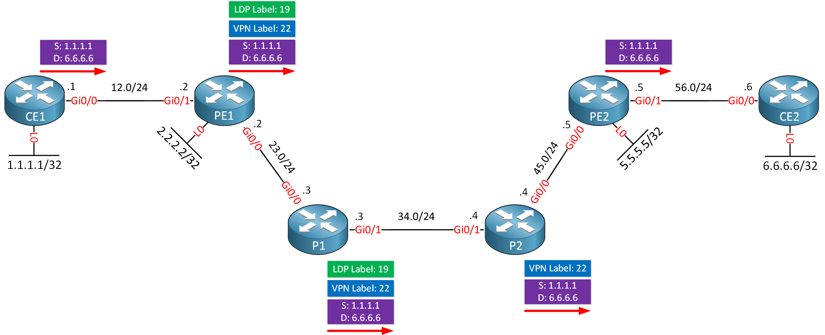
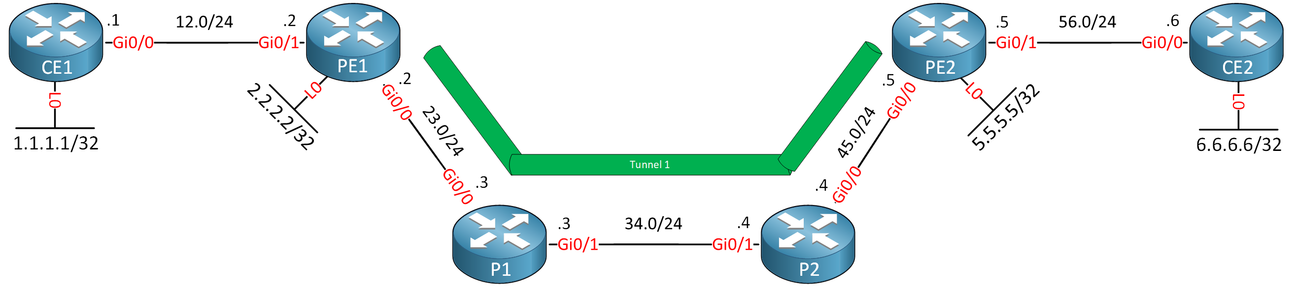
MPLS VPN over PE1-to-PE2 TE tunnel
Let’s look at our first MPLS VPN over TE tunnel scenario, where we create a TE tunnel between PE1 and PE2. The difference between regular MPLS VPN and MPLS VPN over TE tunnels is that we now use the TE tunnel as the next hop.
Let’s create the TE tunnel:
PE1(config)#interface Tunnel1
PE1(config-if)#ip unnumbered Loopback0
PE1(config-if)#tunnel mode mpls traffic-eng
PE1(config-if)#tunnel destination 5.5.5.5
PE1(config-if)#tunnel mpls traffic-eng priority 7 7
PE1(config-if)#tunnel mpls traffic-eng bandwidth 1000
PE1(config-if)#tunnel mpls traffic-eng path-option 1 dynamic
PE1(config-if)#tunnel mpls traffic-eng autoroute announce
I use autoroute announce to install the TE tunnel as the next hop. Let’s check if the tunnel is up:
PE1#show mpls traffic-eng tunnels | include Signal
    Admin: up         Oper: up     Path: valid       Signalling: connected
That seems to be the case. Let’s check prefix 6.6.6.6/32 again:
PE1#show ip route vrf CUSTOMER 6.6.6.6

Routing Table: CUSTOMER
Routing entry for 6.6.6.6/32
  Known via "bgp 1", distance 200, metric 2, type internal
  Redistributing via ospf 1
  Advertised by ospf 1 subnets
  Last update from 5.5.5.5 21:16:13 ago
  Routing Descriptor Blocks:
  * 5.5.5.5 (default), from 5.5.5.5, 21:16:13 ago
      Route metric is 2, traffic share count is 1
      AS Hops 0
      MPLS label: 22
      MPLS Flags: MPLS Required
VPN label 22 remains the same. We still use 5.5.5.5 as the next hop to reach 6.6.6.6. Let’s check that next hop:
PE1#show ip route 5.5.5.5
Routing entry for 5.5.5.5/32
  Known via "isis", distance 115, metric 40, type level-2
  Redistributing via isis
  Last update from 5.5.5.5 on Tunnel1, 00:02:36 ago
  Routing Descriptor Blocks:
  * 5.5.5.5, from 5.5.5.5, 00:02:36 ago, via Tunnel1
      Route metric is 40, traffic share count is 1
We now use the TE tunnel to reach PE2. Let’s check the RSVP transport label we use for this tunnel:
PE1#show mpls traffic-eng tunnels Tunnel 1 | include Label
  InLabel  :  -
  OutLabel : GigabitEthernet0/0, 20
Label 20 has been supplied by RSVP. We now know we use VPN label 22 and RSVP transport label 20.
PE1 forwards the labeled packet to P1, who forwards it like this:
P1#show mpls forwarding-table labels 20
Local      Outgoing   Prefix           Bytes Label   Outgoing   Next Hop
Label      Label      or Tunnel Id     Switched      interface
20         20         2.2.2.2 1 [2]    16447         Gi0/1      192.168.34.4
P1 also uses label 20 and forwards it to P2:
P2#show mpls forwarding-table labels 20
Local      Outgoing   Prefix           Bytes Label   Outgoing   Next Hop
Label      Label      or Tunnel Id     Switched      interface
20         Pop Label  2.2.2.2 1 [2]    15504         Gi0/0      192.168.45.5
P2 pops label 20 and forwards a packet with the VPN label left to PE2. Nothing has changed for PE2:
PE2#show ip bgp vpnv4 all 6.6.6.6
BGP routing table entry for 1:1:6.6.6.6/32, version 7
Paths: (1 available, best #1, table CUSTOMER)
  Advertised to update-groups:
     1
  Refresh Epoch 1
  Local
    192.168.56.6 (via vrf CUSTOMER) from 0.0.0.0 (5.5.5.5)
      Origin incomplete, metric 2, localpref 100, weight 32768, valid, sourced, best
      Extended Community: RT:1:1 OSPF DOMAIN ID:0x0005:0x000000010200
        OSPF RT:0.0.0.0:2:0 OSPF ROUTER ID:192.168.56.5:0
      mpls labels in/out 22/nolabel
      rx pathid: 0, tx pathid: 0x0
PE2 removes the VPN label and forwards the packet without any labels to CE2:
PE2#show ip route vrf CUSTOMER 192.168.56.6

Routing Table: CUSTOMER
Routing entry for 192.168.56.0/24
  Known via "connected", distance 0, metric 0 (connected, via interface)
  Redistributing via bgp 1
  Advertised by bgp 1
  Routing Descriptor Blocks:
  * directly connected, via GigabitEthernet0/1
      Route metric is 0, traffic share count is 1
You can see the labels with a traceroute as well:
CE1#traceroute 6.6.6.6 source loopback 0 numeric probe 1
Type escape sequence to abort.
Tracing the route to 6.6.6.6
VRF info: (vrf in name/id, vrf out name/id)
  1 192.168.12.2 2 msec
  2 192.168.23.3 [MPLS: Labels 20/22 Exp 0] 5 msec
  3 192.168.34.4 [MPLS: Labels 20/22 Exp 0] 5 msec
  4 192.168.56.5 [MPLS: Label 22 Exp 0] 5 msec
  5 192.168.56.6 5 msec
Here is a visualization:
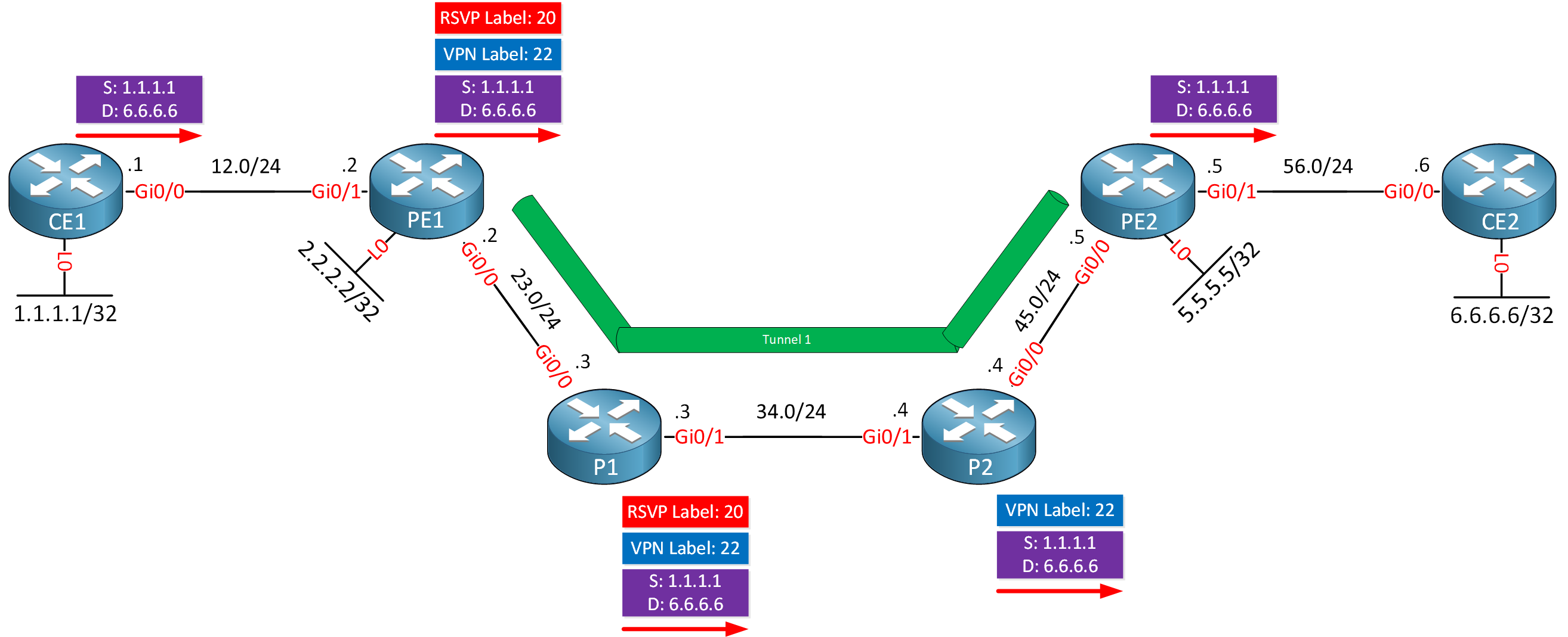
Everything still works. The only difference is that we now use the RSVP label as the transport label instead the LDP label. Before we continue, let’s shut that tunnel:
PE1(config)#interface Tunnel 1
PE1(config-if)#shutdown
MPLS VPN over PE1-to-P2 TE tunnel
This scenario is where it gets interesting. This time, we create a TE tunnel from PE1 to P2:
Let’s create a new tunnel. The configuration is similar to tunnel two except for the tunnel destination:
PE1(config)#interface Tunnel 2
PE1(config-if)#ip unnumbered Loopback0
PE1(config-if)#tunnel mode mpls traffic-eng
PE1(config-if)#tunnel destination 4.4.4.4
PE1(config-if)#tunnel mpls traffic-eng autoroute announce
PE1(config-if)#tunnel mpls traffic-eng priority 7 7
PE1(config-if)#tunnel mpls traffic-eng bandwidth 1000
PE1(config-if)#tunnel mpls traffic-eng path-option 1 dynamic
The tunnel is up:
PE1#show mpls traffic-eng tunnels Tunnel 2 | include Signalling
    Admin: up         Oper: up     Path: valid       Signalling: connected
Let’s try a ping between the loopback interfaces of CE1 and CE2:
CE1#ping 6.6.6.6 source 1.1.1.1 repeat 1
Type escape sequence to abort.
Sending 1, 100-byte ICMP Echos to 6.6.6.6, timeout is 2 seconds:
Packet sent with a source address of 1.1.1.1
.
Success rate is 0 percent (0/1)
This ping fails but why? Let’s go through everything again. PE1 learned about 6.6.6.6/32 through BGP:
PE1#show ip route vrf CUSTOMER 6.6.6.6

Routing Table: CUSTOMER
Routing entry for 6.6.6.6/32
  Known via "bgp 1", distance 200, metric 2, type internal
  Redistributing via ospf 1
  Advertised by ospf 1 subnets
  Last update from 5.5.5.5 01:44:43 ago
  Routing Descriptor Blocks:
  * 5.5.5.5 (default), from 5.5.5.5, 01:44:43 ago
      Route metric is 2, traffic share count is 1
      AS Hops 0
      MPLS label: 22
      MPLS Flags: MPLS Required
We have VPN label 22, and 5.5.5.5 is our next hop. Let’s check how to reach 5.5.5.5:
PE1#show ip route 5.5.5.5
Routing entry for 5.5.5.5/32
  Known via "isis", distance 115, metric 40, type level-2
  Redistributing via isis
  Last update from 4.4.4.4 on Tunnel2, 00:22:48 ago
  Routing Descriptor Blocks:
  * 4.4.4.4, from 5.5.5.5, 00:22:48 ago, via Tunnel2
      Route metric is 40, traffic share count is 1
We use tunnel two to reach 5.5.5.5. Here is the RSVP transport label we learned for tunnel two:
Hello David
In an IPv6 MPLS VPN scenario with TE enabled, several specific configurations are necessary to ensure that IPv6 traffic can be sent between CEs. If IPv6 routes are exchanged through the VRF without TE but traffic is not flowing when TE is enabled, it indicates that there may be missing or incorrect configurations related to MPLS TE for IPv6.
One question I do have, is what do you mean when you say “if IPv6 traffic cannot be sent between CEs?” What is preventing the IPv6 traffic?
In order to be able to further help you in this scenario, let us know
... Continue reading in our forum