Lesson Contents
Diffserv-Aware MPLS TE (DS-TE) is an enhancement to “regular” MPLS TE, making it QoS-aware. This allows headend routers to choose a better path for their TE tunnels.
Regular MPLS TE uses constraint-based-routing (CBR). One of the constraints is bandwidth. MPLS TE routers advertise the available bandwidth on their interfaces. This allows a headend router to use admission control when it wants to establish a new tunnel and select the best possible path.
Thanks to MPLS TE, we can send traffic down paths other than our IGP shortest path. However, there is one issue with “regular” MPLS TE. It doesn’t know and care about QoS. MPLS TE routers don’t know or care whether your packets have any DSCP or EXP markings or if there is any congestion in the network.
In this lesson, we’ll look at a before and after scenario where you’ll learn how MPLS TE DS-TE can make better decisions than regular MPLS TE.
Regular MPLS TE
Let’s look at an example. Here is our topology:
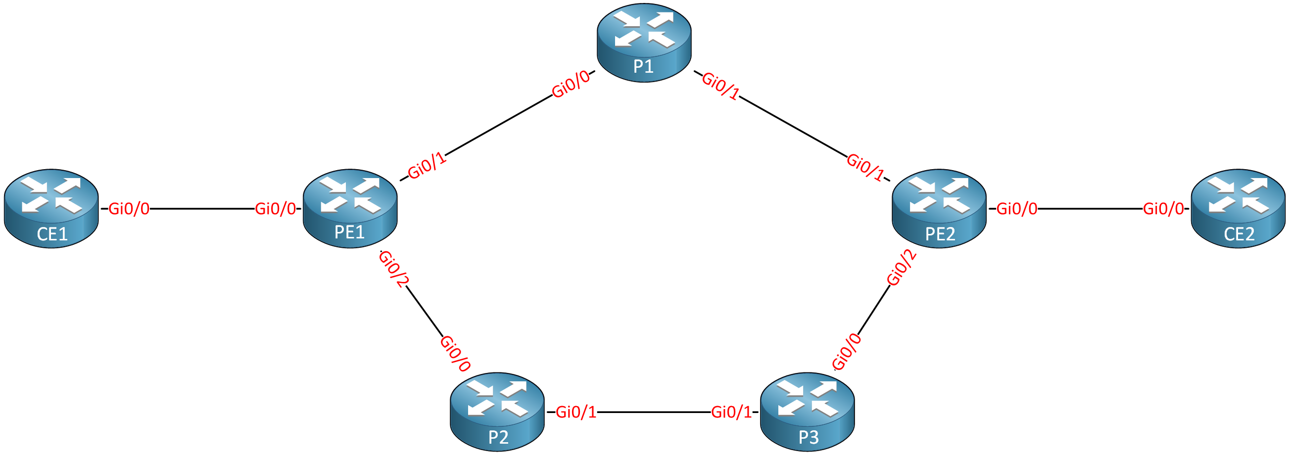
This service provider network uses MPLS TE on all PE and P routers. Let’s say that this SP supports regular data traffic and high-priority traffic, like VoIP. To accomplish this, the SP configures a 400 Mbps priority queue on the interfaces of all PE and P routers. This SP also uses LLQ with a 400Mbps priority queue for VoIP traffic on all interfaces.
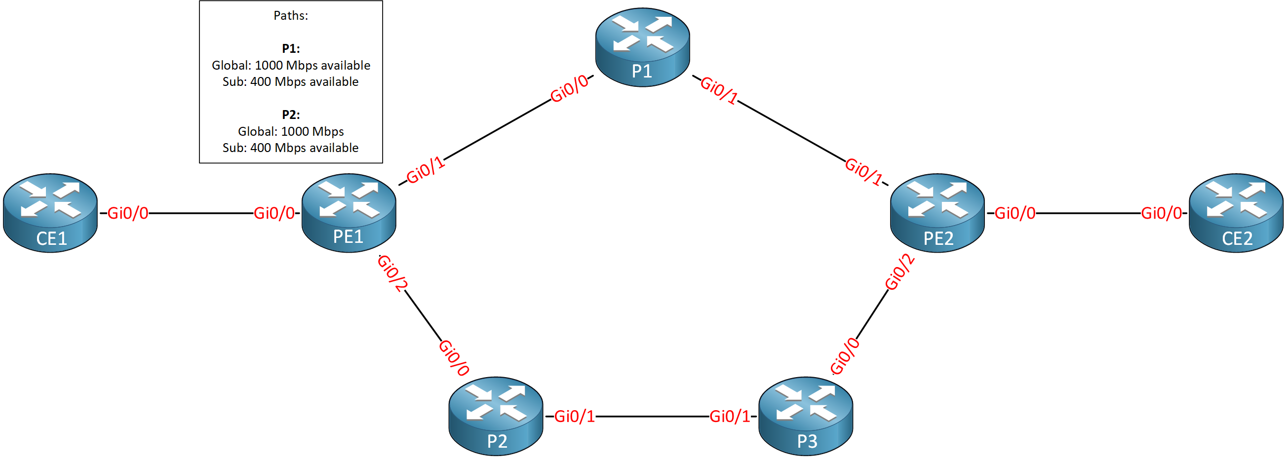
We use Gigabit interfaces everywhere. Assuming RSVP can reserve up to the interface bandwidth, we have 1000 Mbit of bandwidth we can use for tunnel reservations:
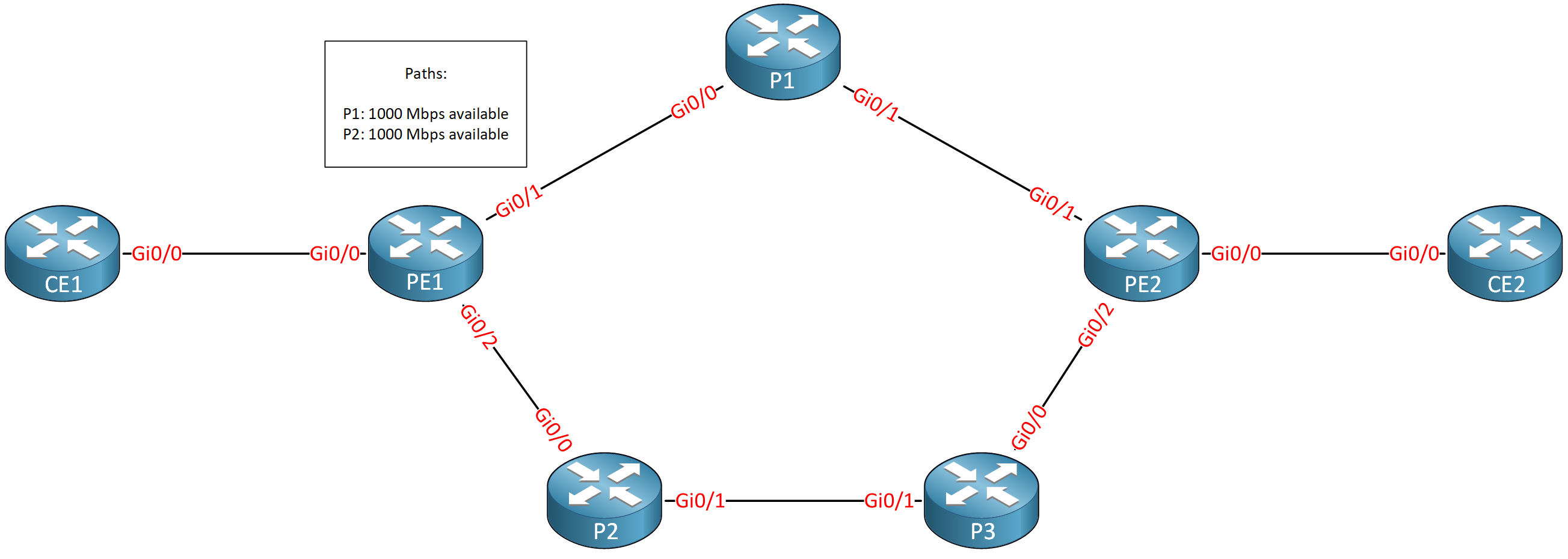
Let’s say the PE1 router wants to establish a TE tunnel to PE2 for VoIP traffic:
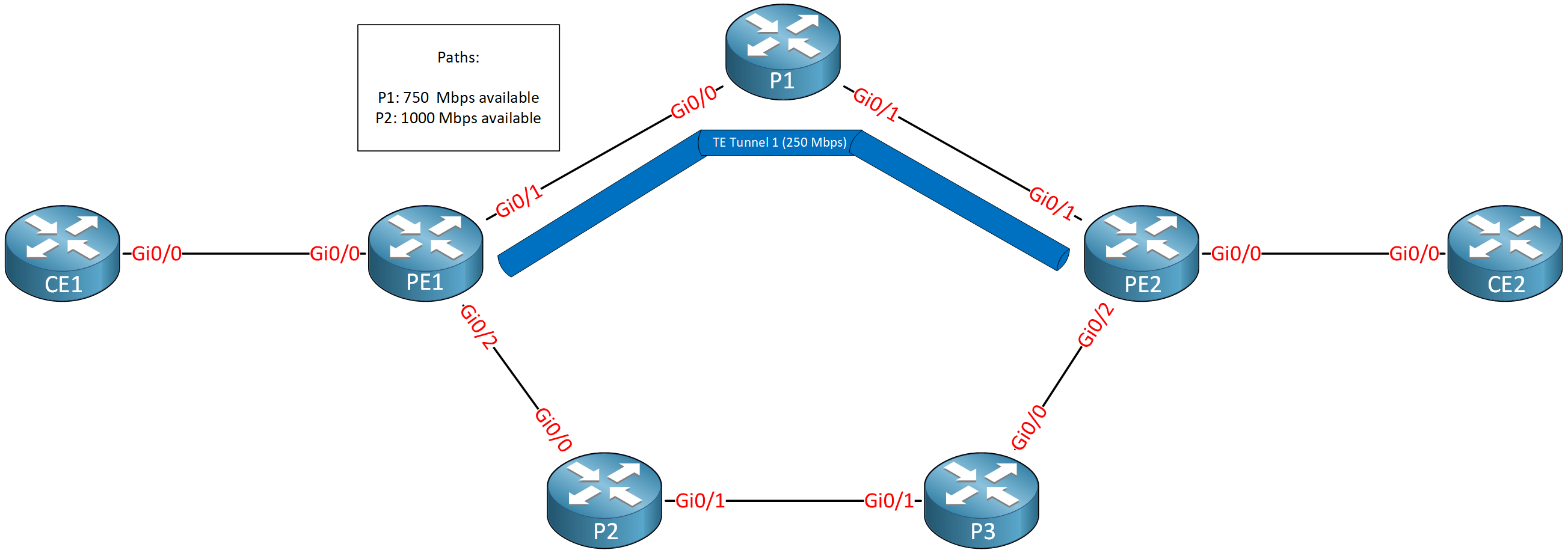
The tunnel requires 250 Mbps of bandwidth. There is enough bandwidth, so PE1 selects the shortest path through P1. This path now has 750 Mbps left. At this moment, we have no issues. Even if there is congestion, our priority queue provides 400 Mbps, while we only need 250 Mbps for tunnel one. Let’s create one more TE tunnel for VoIP traffic:
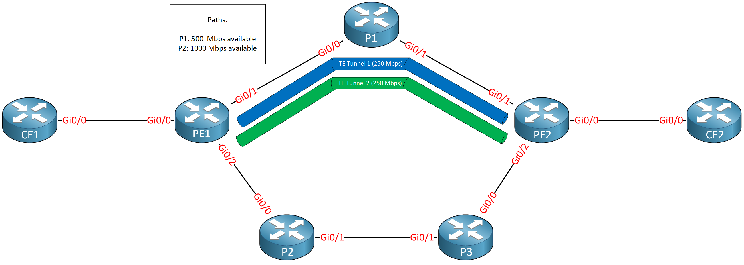
Since there is enough bandwidth (750 Mbps – 250 Mbps = 500 Mbps left) through the path of P1, this is the path that PE1 selects for the second tunnel. We made a reservation for 2x 250 Mbps = 500 Mbps of traffic. The SP has a 400 Mbps priority queue, so in case of congestion, this can happen:
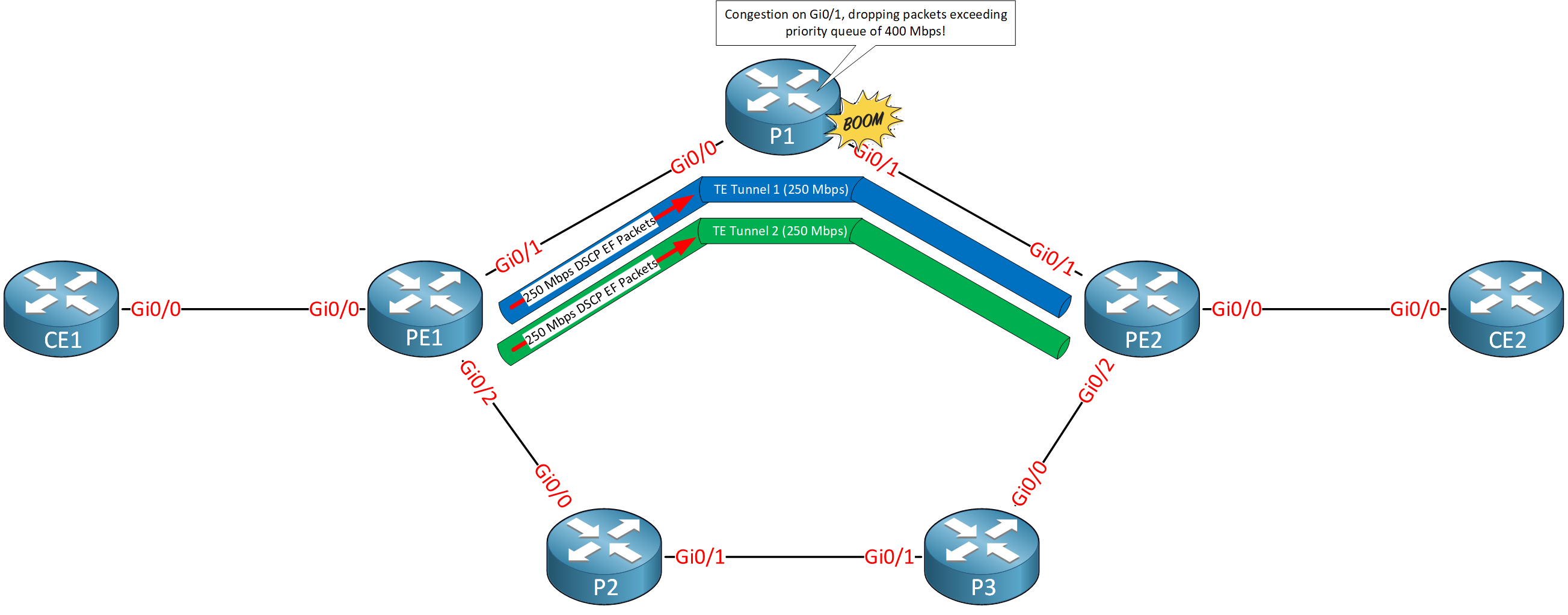
We send 250 Mbps of VoIP traffic through both TE tunnels. The P1 GigabitEthernet 0/1 interface is congested. The priority queue only offers 400 Mbps, so we’ll drop packets in this queue. As a result, all voice calls suffer. PE1 didn’t do anything wrong because everything was fine on the control plane. On the data plane, however, we have an issue.
MPLS TE DS-TE Traditional
MPLS TE uses a single aggregate bandwidth known as the global pool. With DS-TE, we use the global pool and a sub-pool. The sub-pool is a share of the global pool. You can use the sub-pool for high-priority traffic like VoIP and the global pool for everything else.
You can see this sub-pool as a way to advertise bandwidth for a separate queue. For example, you can use it to advertise bandwidth for the priority queue of LLQ. When configuring a tunnel, specify whether you want to use the global pool or sub-pool. Let’s look at an example:
The global pool still has 1000 Mbps of bandwidth. The sub-pool has 400 Mbps and is configured to match the priority queue. Let’s see what happens when we configure tunnel one with a requirement of 250 Mbps of sub-pool bandwidth:
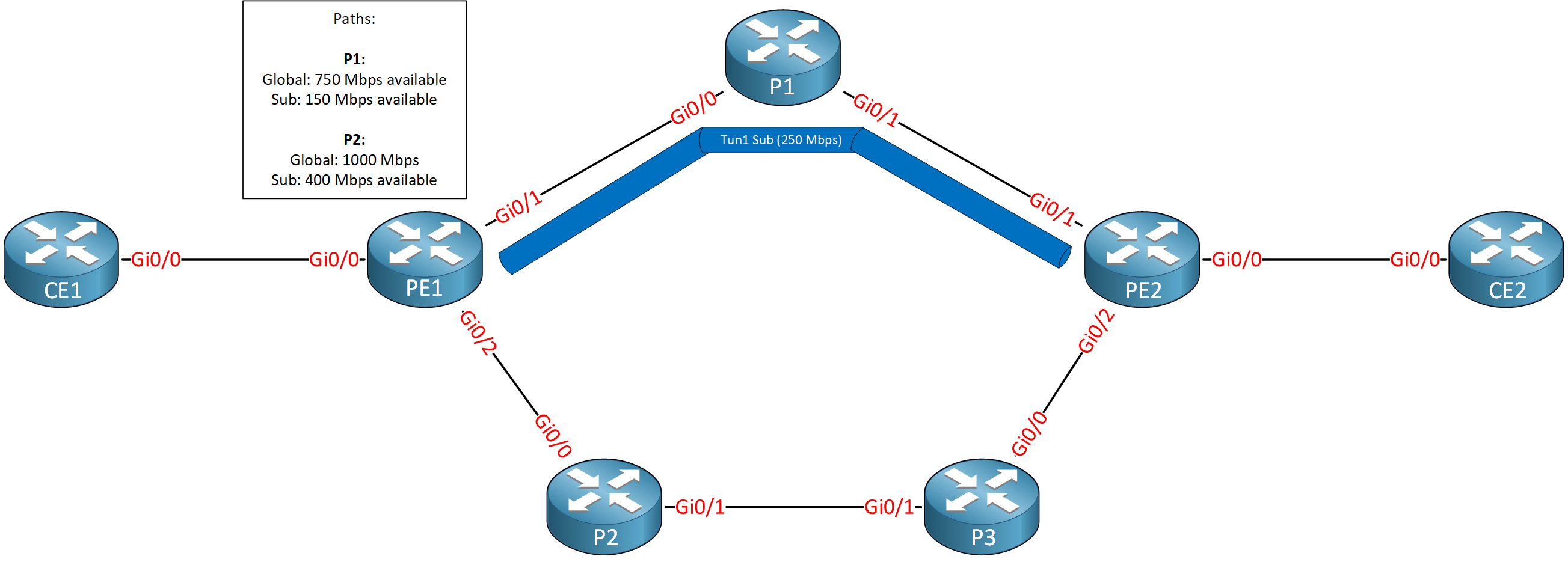
The sub-pool has enough available bandwidth, so PE1 makes a reservation for the shortest path through P1. This reduces the global pool and sub-pool bandwidth by 250 Mbps. Now let’s create tunnel two with 250 Mbps of sub-pool bandwidth:
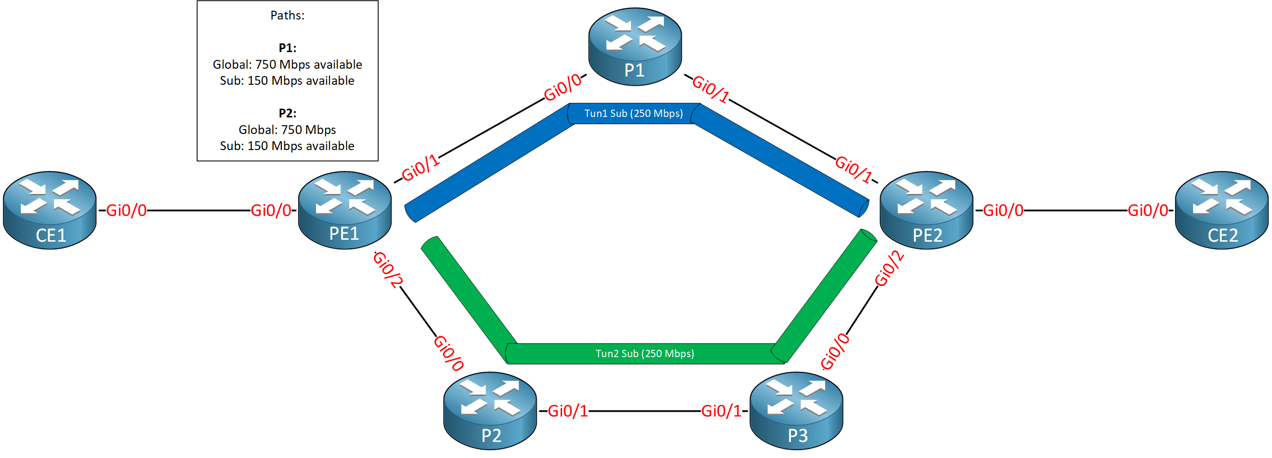
The sub-pool bandwidth through P1 is insufficient for tunnel two, so PE1 looks for another path. The path through P2 and P3 has enough sub-pool bandwidth. The paths through P1 and P2 now only have 150 Mbps of sub-pool bandwidth left. If you try to create another tunnel requiring more than 150 Mbps of sub-pool bandwidth, it will be declined.
The global pool still has more than enough bandwidth. We could create another tunnel that requests global pool bandwidth. For example:
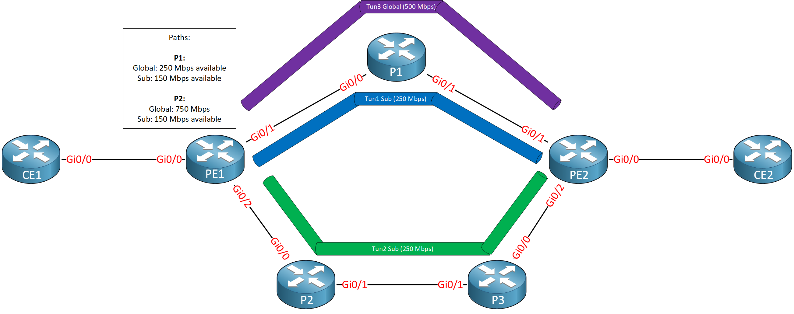
The paths through P1 and P2 have 1000 – 250 = 750 Mbps of global pool bandwidth left. P1 has the shortest path, so that’s the path we use for tunnel three.
Configuration
Enough theoretical talk for now. Let’s look at how to configure MPLS DS-TE. This is the topology we’ll use:

Routers PE1, P1, P2, P3, and PE2 run MPLS TE. Imagine that this service provider network uses a 400 Mbps priority queue for VoIP traffic on all these router interfaces.
I use IOSv Software (VIOS-ADVENTERPRISEK9-M), Version 15.9(3)M6, RELEASE SOFTWARE (fc1) on all routers. We’ll look at a “before” and “after” scenario so you can see why DS-TE is useful.
Configurations
Want to take a look for yourself? Here you will find the startup configuration of each device.
CE1
hostname CE1
!
ip cef
!
interface Loopback0
 ip address 1.1.1.1 255.255.255.255
 ip router isis
 isis circuit-type level-2-only
!
interface GigabitEthernet0/0
 ip address 192.168.12.1 255.255.255.0
 ip router isis
 isis circuit-type level-2-only
!
router isis
 net 49.0001.0001.0001.0001.0001.00
 is-type level-2-only
 metric-style wide
!
end
CE2
hostname CE2
!
ip cef
!
interface Loopback0
 ip address 7.7.7.7 255.255.255.255
 ip router isis
 isis circuit-type level-2-only
!
interface GigabitEthernet0/0
 ip address 192.168.67.7 255.255.255.0
 ip router isis
 isis circuit-type level-2-only
!
router isis
 mpls traffic-eng level-2
 net 49.0001.0007.0007.0007.0007.00
 is-type level-2-only
 metric-style wide
!
end
P1
hostname P1
!
ip cef
!
mpls traffic-eng tunnels
!
interface Loopback0
 ip address 3.3.3.3 255.255.255.255
 ip router isis
 isis circuit-type level-2-only
!
interface GigabitEthernet0/0
 ip address 192.168.23.3 255.255.255.0
 ip router isis
 mpls traffic-eng tunnels
 mpls ip
 isis circuit-type level-2-only
 ip rsvp bandwidth 1000000
!
interface GigabitEthernet0/1
 ip address 192.168.36.3 255.255.255.0
 ip router isis
 mpls traffic-eng tunnels
 mpls ip
 isis circuit-type level-2-only
 ip rsvp bandwidth 1000000
!
router isis
 mpls traffic-eng router-id Loopback0
 mpls traffic-eng level-2
 net 49.0001.0003.0003.0003.0003.00
 is-type level-2-only
 metric-style wide
!
mpls ldp router-id Loopback0 force
!
end
P2
hostname P2
!
ip cef
!
mpls traffic-eng tunnels
!
interface Loopback0
 ip address 4.4.4.4 255.255.255.255
 ip router isis
 isis circuit-type level-2-only
!
interface GigabitEthernet0/0
 ip address 192.168.24.4 255.255.255.0
 ip router isis
 mpls traffic-eng tunnels
 mpls ip
 isis circuit-type level-2-only
 ip rsvp bandwidth 1000000
!
interface GigabitEthernet0/1
 ip address 192.168.45.4 255.255.255.0
 ip router isis
 mpls traffic-eng tunnels
 mpls ip
 isis circuit-type level-2-only
 ip rsvp bandwidth 1000000
!
router isis
 mpls traffic-eng router-id Loopback0
 mpls traffic-eng level-2
 net 49.0001.0004.0004.0004.0004.00
 is-type level-2-only
 metric-style wide
!
mpls ldp router-id Loopback0 force
!
end
P3
hostname P3
!
ip cef
!
mpls traffic-eng tunnels
!
interface Loopback0
 ip address 5.5.5.5 255.255.255.255
 ip router isis
 isis circuit-type level-2-only
!
interface GigabitEthernet0/0
 ip address 192.168.56.5 255.255.255.0
 ip router isis
 mpls traffic-eng tunnels
 mpls ip
 isis circuit-type level-2-only
 ip rsvp bandwidth 1000000
!
interface GigabitEthernet0/1
 ip address 192.168.45.5 255.255.255.0
 ip router isis
 mpls traffic-eng tunnels
 mpls ip
 isis circuit-type level-2-only
 ip rsvp bandwidth 1000000
!
router isis
 mpls traffic-eng router-id Loopback0
 mpls traffic-eng level-2
 net 49.0001.0005.0005.0005.0005.00
 is-type level-2-only
 metric-style wide
!
mpls ldp router-id Loopback0 force
!
end
PE1
hostname PE1
!
ip cef
!
mpls traffic-eng tunnels
!
interface Loopback0
 ip address 2.2.2.2 255.255.255.255
 ip router isis
 isis circuit-type level-2-only
!
interface GigabitEthernet0/0
 ip address 192.168.12.2 255.255.255.0
 ip router isis
 isis circuit-type level-2-only
!
interface GigabitEthernet0/1
 ip address 192.168.23.2 255.255.255.0
 ip router isis
 mpls traffic-eng tunnels
 mpls ip
 isis circuit-type level-2-only
 ip rsvp bandwidth 1000000
!
interface GigabitEthernet0/2
 ip address 192.168.24.2 255.255.255.0
 ip router isis
 mpls traffic-eng tunnels
 mpls ip
 isis circuit-type level-2-only
 ip rsvp bandwidth 1000000
!
interface GigabitEthernet0/3
 no ip address
!
router isis
 mpls traffic-eng router-id Loopback0
 mpls traffic-eng level-2
 net 49.0001.0002.0002.0002.0002.00
 is-type level-2-only
 metric-style wide
!
mpls ldp router-id Loopback0 force
!
end
PE2
hostname PE2
!
ip cef
!
mpls traffic-eng tunnels
!
interface Loopback0
 ip address 6.6.6.6 255.255.255.255
 ip router isis
 isis circuit-type level-2-only
!
interface GigabitEthernet0/0
 ip address 192.168.67.6 255.255.255.0
 ip router isis
 isis circuit-type level-2-only
!
interface GigabitEthernet0/1
 ip address 192.168.36.6 255.255.255.0
 ip router isis
 mpls traffic-eng tunnels
 mpls ip
 isis circuit-type level-2-only
 ip rsvp bandwidth 1000000
!
interface GigabitEthernet0/2
 ip address 192.168.56.6 255.255.255.0
 ip router isis
 mpls traffic-eng tunnels
 mpls ip
 isis circuit-type level-2-only
 ip rsvp bandwidth 1000000
!
router isis
 mpls traffic-eng router-id Loopback0
 mpls traffic-eng level-2
 net 49.0001.0006.0006.0006.0006.00
 is-type level-2-only
 metric-style wide
!
mpls ldp router-id Loopback0 force
!
end
Regular MPLS TE
We’ll start with regular MPLS. We use the global pool, and we don’t have any tunnels yet. Let’s check the interfaces of PE1:
Hi everybody
I got an error that from tunnel1 and tunnel2
no routing dynamic
?
Hello Bahri
When it comes to MPLS TE, the dynamic nature of the setup means that dynamic routing protocols should be correctly enabled and configured, and that the tunnels be configured with the dynamic path-option like so:
PE1(config-if)#tunnel mpls traffic-eng path-option 1 dynamicThis will enable the tunnel path to dynamically conform to the path with the lowest metric based on the IGP deployed. For more info on this command, take a look at this Cisco command reference:
https://www.cisco.com/c/en/us/td/docs/ios-xml/ios/mpls/command/mp-cr-book/mp-t1.html#wp2
... Continue reading in our forumhttps://cdn-forum.networklessons.com/uploads/default/original/2X/3/3ef3fa14d5a2baa82fb71da7203b3928277364ec.jpeg
Dear team , bit confused about below scenario .I hope You guys can clear it.
Let’s assume there are two LLQs on P1’s Gi0/1 — LLQ priority level 1 for voice (300 kbps) and LLQ priority level 2 for video (400 kbps). In this case, how can I configure RSVP on all interfaces to have a global pool, a sub-pool, and tunnel bandwidth?
Hello Ratheesh
The scenario you refer to deals with DiffServ-aware Traffic Engineering for MPLS, or DS-TE MPLS. This is an enhancement to standard MPLS-TE. In MPLS-TE, you can reserve bandwidth for tunnels but all reservations come from the same single “global” bandwidth pool. This means that high-priority traffic (like voice or video) could be blocked if lower-priority tunnels have already consumed the available TE bandwidth.
DS-TE introduces the concept of multiple bandwidth pools, allowing you to create a global pool, as well as sub-pools. You can define
... Continue reading in our forum