Lesson Contents
In the MPLS Traffic Engineering (TE) IS-IS Configuration lesson and other MPLS TE lessons, I use IS-IS as the IGP on the TE routers. In this lesson, we’ll use OSPF instead.
I’ll walk you through the entire configuration, but because I already explained in detail how to configure an MPLS TE network step-by-step, I’ll only focus on OSPF here. This is the topology we’ll use:
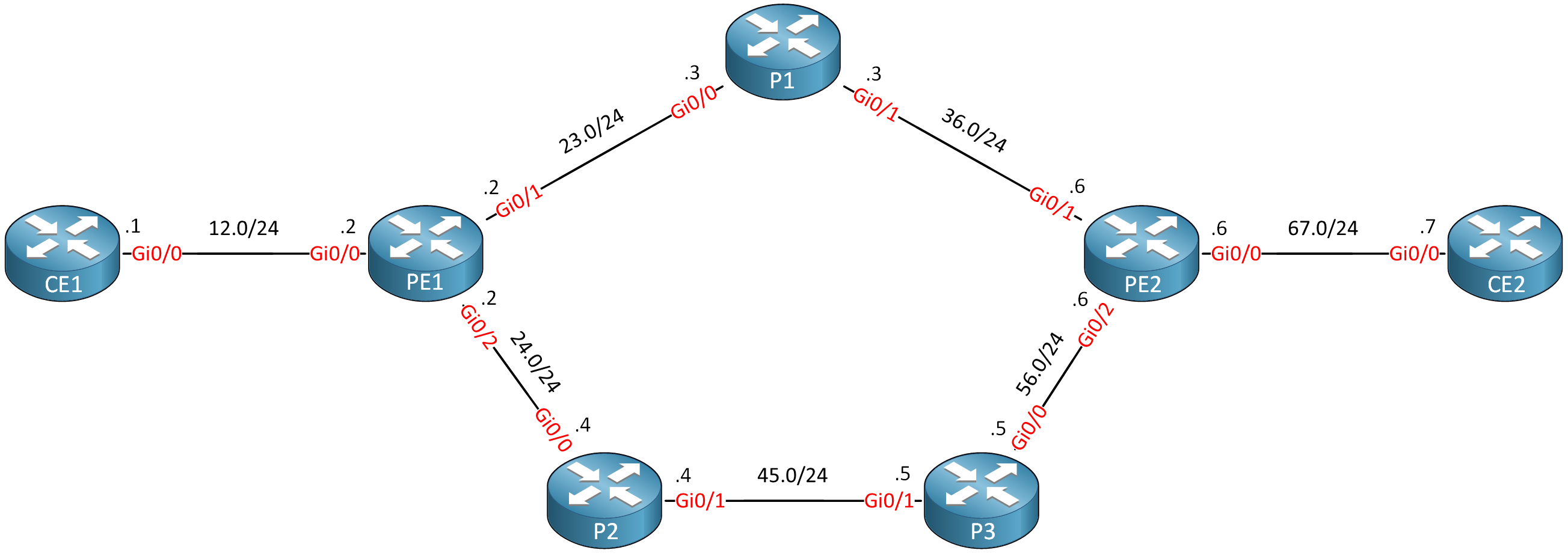
Routers PE1, P1, P2, P3, and PE2 are our MPLS core network. The CE1 and CE2 routers use regular IP routing. All routers are configured to use OSPF area 0 and MPLS is enabled on the interfaces. I use Cisco IOS Software, IOSv Software (VIOS-ADVENTERPRISEK9-M), Version 15.9(3)M4.
Configurations
Want to take a look for yourself? Here, you will find the startup configuration of each device.
CE1
hostname CE1
!
ip cef
!
interface Loopback0
 ip address 1.1.1.1 255.255.255.255
!
interface GigabitEthernet0/0
 ip address 192.168.12.1 255.255.255.0
!
router ospf 1
 network 1.1.1.1 0.0.0.0 area 0
 network 192.168.12.0 0.0.0.255 area 0
!
end
CE2
hostname CE2
!
ip cef
!
interface Loopback0
 ip address 7.7.7.7 255.255.255.255
!
interface GigabitEthernet0/0
 ip address 192.168.67.7 255.255.255.0
!
router ospf 1
 network 7.7.7.7 0.0.0.0 area 0
 network 192.168.67.0 0.0.0.255 area 0
!
end
P1
hostname P1
!
ip cef
!
interface Loopback0
 ip address 3.3.3.3 255.255.255.255
!
interface GigabitEthernet0/0
 ip address 192.168.23.3 255.255.255.0
 mpls ip
!
interface GigabitEthernet0/1
 ip address 192.168.36.3 255.255.255.0
 mpls ip
!
router ospf 1
 network 3.3.3.3 0.0.0.0 area 0
 network 192.168.23.0 0.0.0.255 area 0
 network 192.168.36.0 0.0.0.255 area 0
!
mpls ldp router-id Loopback0 force
!
end
P2
hostname P2
!
ip cef
!
interface Loopback0
 ip address 4.4.4.4 255.255.255.255
!
interface GigabitEthernet0/0
 ip address 192.168.24.4 255.255.255.0
 mpls ip
!
interface GigabitEthernet0/1
 ip address 192.168.45.4 255.255.255.0
 mpls ip
!
router ospf 1
 network 4.4.4.4 0.0.0.0 area 0
 network 192.168.24.0 0.0.0.255 area 0
 network 192.168.45.0 0.0.0.255 area 0
!
mpls ldp router-id Loopback0 force
!
end
P3
hostname P3
!
ip cef
!
interface Loopback0
 ip address 5.5.5.5 255.255.255.255
!
interface GigabitEthernet0/0
 ip address 192.168.56.5 255.255.255.0
 mpls ip
!
interface GigabitEthernet0/1
 ip address 192.168.45.5 255.255.255.0
 mpls ip
!
router ospf 1
 network 5.5.5.5 0.0.0.0 area 0
 network 192.168.45.0 0.0.0.255 area 0
 network 192.168.56.0 0.0.0.255 area 0
!
mpls ldp router-id Loopback0 force
!
end
PE1
hostname PE1
!
ip cef
!
interface Loopback0
 ip address 2.2.2.2 255.255.255.255
!
interface GigabitEthernet0/0
 ip address 192.168.12.2 255.255.255.0
!
interface GigabitEthernet0/1
 ip address 192.168.23.2 255.255.255.0
 mpls ip
!
interface GigabitEthernet0/2
 ip address 192.168.24.2 255.255.255.0
 mpls ip
!
router ospf 1
 network 2.2.2.2 0.0.0.0 area 0
 network 192.168.12.0 0.0.0.255 area 0
 network 192.168.23.0 0.0.0.255 area 0
 network 192.168.24.0 0.0.0.255 area 0
!
mpls ldp router-id Loopback0 force
!
end
PE2
hostname PE2
!
ip cef
!
interface Loopback0
 ip address 6.6.6.6 255.255.255.255
!
interface GigabitEthernet0/0
 ip address 192.168.67.6 255.255.255.0
!
interface GigabitEthernet0/1
 ip address 192.168.36.6 255.255.255.0
 mpls ip
!
interface GigabitEthernet0/2
 ip address 192.168.56.6 255.255.255.0
 mpls ip
!
router ospf 1
 network 6.6.6.6 0.0.0.0 area 0
 network 192.168.36.0 0.0.0.255 area 0
 network 192.168.56.0 0.0.0.255 area 0
 network 192.168.67.0 0.0.0.255 area 0
!
mpls ldp router-id Loopback0 force
!
end
Before we continue, let’s make sure we have a label-switched path (LSP) when we send traffic from CE1 to CE2:
CE1#traceroute 7.7.7.7 source 1.1.1.1 probe 1
Type escape sequence to abort.
Tracing the route to 7.7.7.7
VRF info: (vrf in name/id, vrf out name/id)
  1 192.168.12.2 1 msec
  2 192.168.23.3 [MPLS: Label 23 Exp 0] 4 msec
  3 192.168.36.6 [MPLS: Label 19 Exp 0] 3 msec
  4 192.168.67.7 4 msec
The LSP is working.
Configuration
Let’s configure this “regular” MPLS network into a network that supports MPLS TE. There are four main items we have to configure:
- Enable MPLS TE support:
- Globally
- Interfaces
- Configure OSPF to support MPLS TE.
- Configure RSVP.
- Configure a TE tunnel interface.
We configure these items on all MPLS routers where you want to use MPLS TE. Let’s get started.
Global
The global mpls traffic-eng tunnels command enables MPLS TE globally:
PE1, P1, P2, P3, and PE2
(config)#mpls traffic-eng tunnels
Interfaces
We have to enable MPLS TE support on all interfaces that connect the PE and P routers:
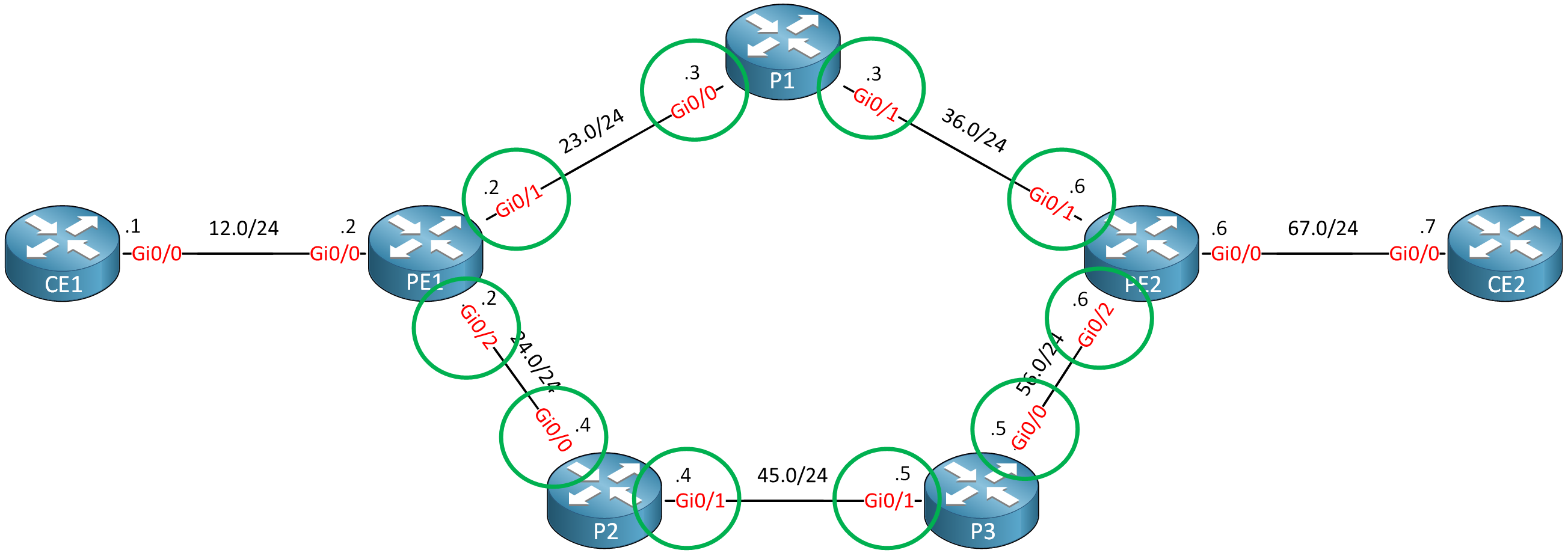
This is the configuration:
PE1 and PE2
(config)#interface range GigabitEthernet 0/1 - 2
(config-if-range)#mpls traffic-eng tunnels
P1, P2, and P3
(config)#interface range GigabitEthernet 0/0 - 1
(config-if-range)#mpls traffic-eng tunnelsThat’s all you need.
OSPF
There are two things we need to configure for OSPF to support MPLS TE:
- Enable MPLS TE for the area.
- Configure the router ID.
Here’s how to do it:
PE1, PE2, P1, P2 & P3
(config)#router ospf 1
(config-router)#mpls traffic-eng area 0
(config-router)#mpls traffic-eng router-id loopback 0
RSVP
Let’s configure RSVP to use up to the interface bandwidth:
PE1 and PE2
(config)#interface range GigabitEthernet 0/1 - 2
(config-if-range)#ip rsvp bandwidth 1000000
P1, P2, and P3
(config)#interface range GigabitEthernet 0/0 - 1
(config-if-range)#ip rsvp bandwidth 1000000Tunnel Interface
Let’s configure a tunnel interface between PE1 and PE2:
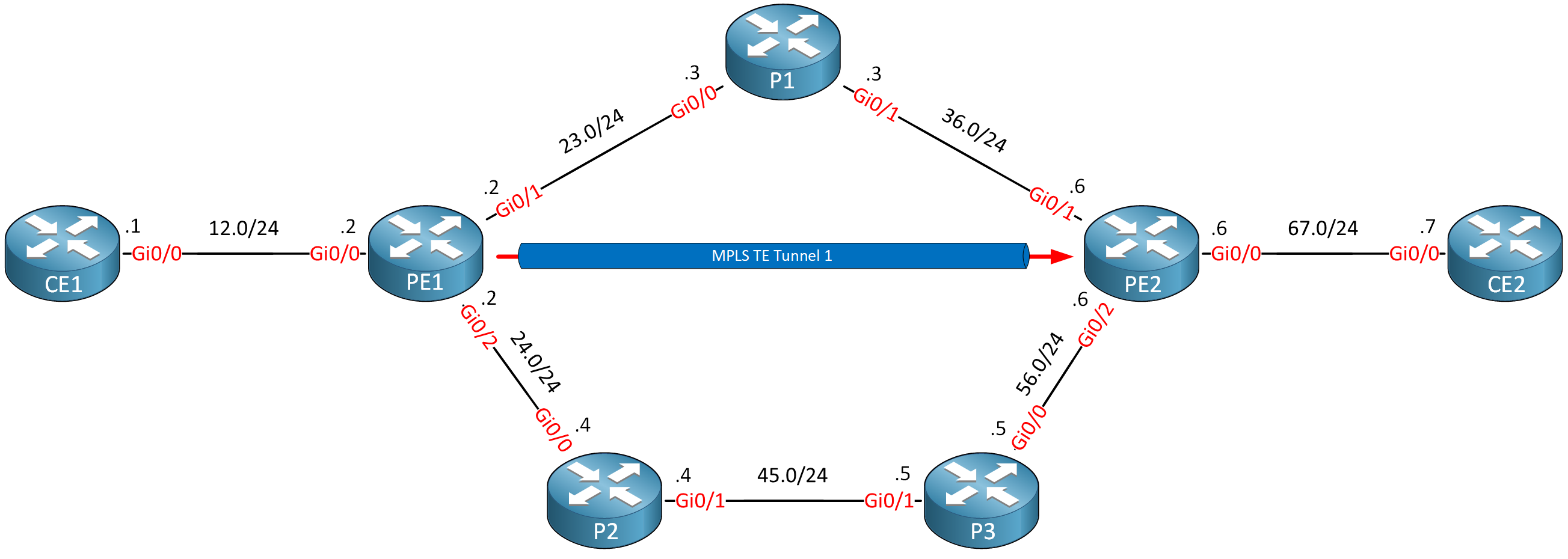
This is how you configure a tunnel interface:
PE1(config)#interface Tunnel 1
PE1(config-if)#ip unnumbered Loopback 0
PE1(config-if)#tunnel mode mpls traffic-eng
PE1(config-if)#tunnel destination 6.6.6.6
PE1(config-if)#tunnel mpls traffic-eng bandwidth 750
PE1(config-if)#tunnel mpls traffic-eng path-option 1 dynamic
Verification
Everything is now configured. This network should be ready for MPLS TE. Let’s find out.
Dear, i got this while following your tutorial
... Continue reading in our forumHello Mehdi
You attempted to issue the following command:
PE1(config)#mpls traffic-eng area 0However, you are in global configuration mode. This command is only available under OSPF configuration mode. So the correct method, as shown in the lesson is to do this:
The above command is issued under the OSPF configuration mode which is entered using the
router ospf 1command. So yes, you should issue the commands you suggested instead.I hope this has been helpful!
Laz
Hello Zaygham
You are correct that RSVP can indeed generate labels. However, in an MPLS-TE configuration using OSPF, both LDP and RSVP can be used, but when they’re used together, they serve different purposes. Here’s a detailed explanation of why both are often used together:
Here are some reasons to use both Both LDP and RSVP together:
-
- LDP for Standard Traffic: LDP can be used for general-purpose traffic where strict path requirements and resource reservations are not needed. This ensures that basic MPLS forwarding is always available, le
... Continue reading in our forumDual Use Cases: