Lesson Contents
In the MPLS TE Diffserv-Aware (DS-TE) Traditional lesson, we learned how “regular” MPLS TE knows nothing about Quality of Service (QoS) and how we can make it QoS aware. The “traditional” version of DS-TE was the first version, a Cisco proprietary version. Other vendors have similar implementations. This version is also known as “pre-standard.” A few years later, the Internet Engineering Task Force (IETF) introduced a DS-TE version based on different standards. Nowadays, there are three different DS-TE modes:
- Traditional mode: Cisco’s proprietary DS-TE. This has been available since Cisco IOS Release 12.2(33)SRB) and was released in 2008.
- Migration mode: Used for migrating traditional DS-TE to IETF mode DS-TE without tearing down tunnels.
- IETF mode: The latest version is based on IETF standards.
Traditional DS-TE has some limitations and only supports a global pool and sub-pool. The IETF DS-TE version builds upon the traditional DS-TE version and supports multiple class types and bandwidth constraints. There are four main components we have to discuss:
- Class-Types (CT)
- TE Classes
- RSVP
- Bandwidth Constraints Models (BCM)
In this lesson, we’ll dive into these components to understand how MPLS DS-TE IETF mode works. I will also explain how to configure everything so you can see it in action.
Class Types (CT)
A class type (CT) represents traffic requiring a certain service level. For example, VoIP traffic is considered high priority, while regular data traffic is classified as low priority. IETF mode has eight CTs, ranging from CT0 to CT7. We can apply different bandwidth constraints (BC) to each CT.
Cisco currently supports two CTs: CT0 and CT1.
CT0 corresponds to the global pool, while CT1 is the sub-pool.
TE Classes
In “regular” (non-DS-TE) MPLS TE, we calculate a path based on constraints such as bandwidth and attributes such as the setup and hold priority. IGPs advertise these constraints to each other. With IETF mode, there are eight CTs and eight priorities, so that you can have 64 possible combinations. This means IGPs would have to advertise 64 values.
To simplify this, we have TE classes. A TE class combines a CT and a preemption priority.
TE classes must be configured the same on all TE routers. Here is an example:
| TE Class | Class Type | Priority |
|---|---|---|
| 0 | 0 | 7 |
| 1 | 0 | 6 |
| 2 | 1 | 5 |
| 3 | 1 | 4 |
| 4 | 2 | 3 |
| 5 | 2 | 2 |
| 6 | 3 | 1 |
| 7 | 3 | 0 |
We have four CTs (CT0, CT1, CT2, and CT3) and eight priority levels. When you use CT1 and priority 5, we call it TE class 2. If you use CT 3 and priority level 1, we call it TE class 6.
RSVP
When a path is calculated, it is signaled using RSVP-TE. To support the new CTs, we have a new RSVP object called “CLASSTYPE”. This object includes CT values 1-7. If you establish an LSP for CT0, the CLASSTYPE object is not included in the RSVP PATH message. This allows backward compatibility with routers that don’t support DS-TE.
Bandwidth Constraints Model (BCM)
Bandwidth constraints (BC) are the rules a router uses to assign bandwidth to different CTs. When a DS-TE router creates a new TE tunnel, it updates the unreserved bandwidth for each TE class. Traditional DS-TE has two bandwidth constraints:
- Global pool
- Sub-pool
The global pool is the maximum reservable bandwidth (MRB), while the sub-pool is a portion of the global pool.
DS-TE IETF mode supports two different BCMs we can use for DS-TE bandwidth allocation within each class:
- Maximum Allocation Model (MAM)
- Russian Dolls Model (RDM)
Both bandwidth constraint models support up to eight CTs. Let’s look at the differences between the two.
Maximum Allocation Model (MAM)
MAM maps one bandwidth constraint (BC) to one CT.
Here is a visualization:
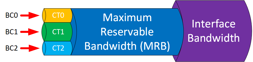
The picture above shows three CTs (CT0, CT1, and CT2). Each CT has its BC. If you use all eight CTs, you have these BCs:
| Bandwidth Constraint | Maximum Bandwidth Allocation For |
|---|---|
| BC7 | CT7 |
| BC6 | CT6 |
| BC5 | CT5 |
| BC4 | CT4 |
| BC3 | CT3 |
| BC2 | CT2 |
| BC1 | CT1 |
| BC0 | CT0 |
Each CT has its BC, and you can’t share bandwidth between CTs.The advantage is that each CT is isolated because it has its own “reservation”. You’ll never run into a scenario where the LSP of one CT preempts the LSP of another CT. The disadvantage of MAM is that we waste bandwidth. One CT can’t use any unused bandwidth that other CTs don’t use. What you’ll see when you use MAM is that sometimes, LSPs won’t be able to select the most optimal path in the network.
Russian Dolls Model (RDM)
RDM maps one BC to one or more CTs. This allows efficient use of available bandwidth because you can share bandwidth between CTs.
Here is a visualization:
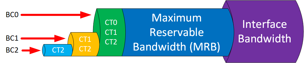
The picture above shows three CTs (CT0, CT1, and CT2). The global pool (BC0) equals the MRB of the interface. Here’s how it works:
- BC2 limits CT2 to a small portion of the bandwidth.
- BC1 limits CT1 + CT2 to a larger portion of the bandwidth.
- BC0 limits CT1 + CT2 + CT3 to the MRB.
RDM supports up to eight CTs. CT7 has the most strict requirements, and CT0 is best-effort traffic. Below is an overview of all CTs and BCs:
| Bandwidth Constraint | Maximum Bandwidth Allocation For |
|---|---|
| BC7 | CT7 |
| BC6 | CT6 + CT7 |
| BC5 | CT5 + CT6 + CT7 |
| BC4 | CT4 + CT5 + CT6 + CT7 |
| BC3 | CT3 + CT4 + CT5 + CT6 + CT7 |
| BC2 | CT2 + CT3 + CT4 + CT5 + CT6 + CT7 |
| BC1 | CT1 + CT2 + CT3 + CT4 + CT5 + CT6 + CT7 |
| BC0 | CT0 + CT1 + CT2 + CT3 + CT4 + CT5 + CT6 + CT7 |
This allows CTs to use bandwidth that others don’t.
Configuration
You now know the basics of MPLS DS-TE IETF mode. Let’s see it in action. To configure all of this, we’ll use this topology:
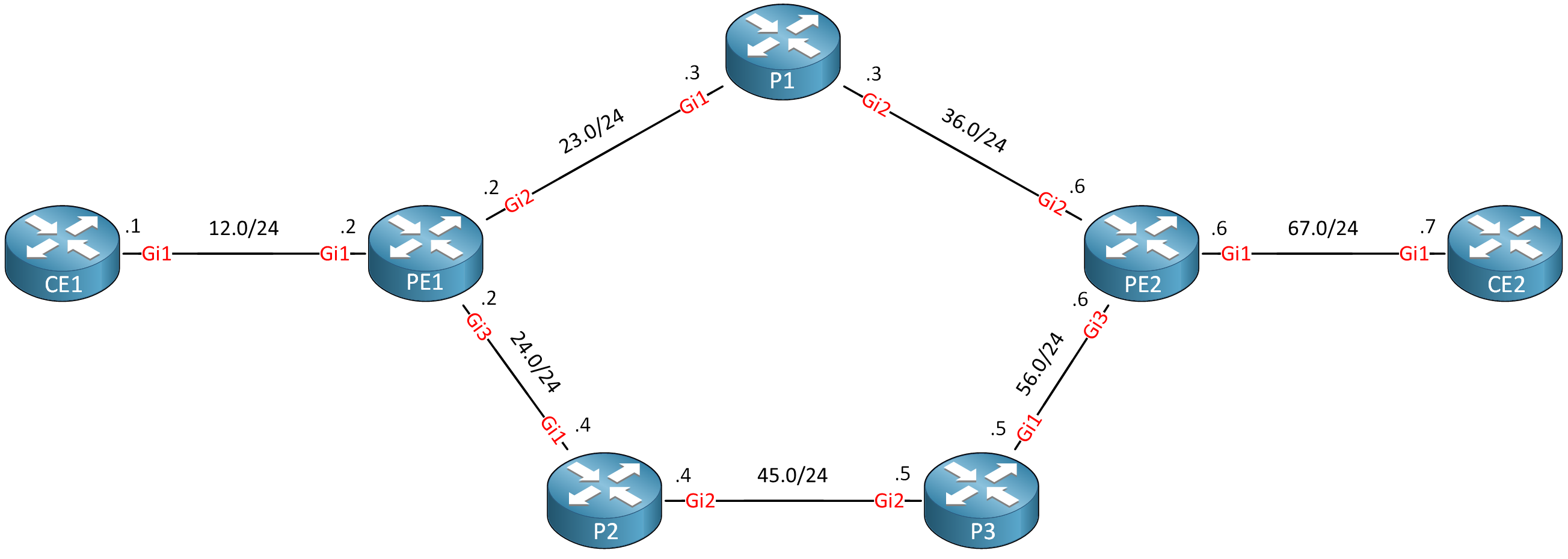
I use Cisco IOS Software [Amsterdam], Virtual XE Software (X86_64_LINUX_IOSD-UNIVERSALK9-M), Version 17.3.6, RELEASE SOFTWARE (fc2) on all routers. We are going to convert a regular non-DS-TE network into IETF mode.
Configurations
Want to take a look for yourself? Here you will find the startup configuration of each device.
CE1
hostname CE1
!
interface Loopback0
 ip address 1.1.1.1 255.255.255.255
 ip router isis
 isis circuit-type level-2-only
!
interface GigabitEthernet1
 ip address 192.168.12.1 255.255.255.0
 ip router isis
 isis circuit-type level-2-only
!
router isis
 net 49.0001.0001.0001.0001.0001.00
 is-type level-2-only
 metric-style wide
!
end
CE2
hostname CE2
!
interface Loopback0
 ip address 7.7.7.7 255.255.255.255
 ip router isis
 isis circuit-type level-2-only
!
interface GigabitEthernet1
 ip address 192.168.67.7 255.255.255.0
 ip router isis
 isis circuit-type level-2-only
!
router isis
 net 49.0001.0007.0007.0007.0007.00
 is-type level-2-only
 metric-style wide
!
end
P1
hostname P1
!
mpls traffic-eng tunnels
!
interface Loopback0
 ip address 3.3.3.3 255.255.255.255
 ip router isis
 isis circuit-type level-2-only
!
interface GigabitEthernet1
 ip address 192.168.23.3 255.255.255.0
 ip router isis
 mpls ip
 mpls traffic-eng tunnels
 isis circuit-type level-2-only
 ip rsvp bandwidth 1000000
!
interface GigabitEthernet2
 ip address 192.168.36.3 255.255.255.0
 ip router isis
 mpls ip
 mpls traffic-eng tunnels
 isis circuit-type level-2-only
 ip rsvp bandwidth 1000000
!
router isis
 net 49.0001.0003.0003.0003.0003.00
 is-type level-2-only
 metric-style wide
 mpls traffic-eng router-id Loopback0
 mpls traffic-eng level-2
!
ip http secure-server
!
mpls ldp router-id Loopback0 force
!
end
P2
hostname P2
!
mpls traffic-eng tunnels
!
interface Loopback0
 ip address 4.4.4.4 255.255.255.255
 ip router isis
 isis circuit-type level-2-only
!
interface GigabitEthernet1
 ip address 192.168.24.4 255.255.255.0
 ip router isis
 mpls ip
 mpls traffic-eng tunnels
 isis circuit-type level-2-only
 ip rsvp bandwidth 1000000
!
interface GigabitEthernet2
 ip address 192.168.45.4 255.255.255.0
 ip router isis
 mpls ip
 mpls traffic-eng tunnels
 isis circuit-type level-2-only
 ip rsvp bandwidth 1000000
!
router isis
 net 49.0001.0004.0004.0004.0004.00
 is-type level-2-only
 metric-style wide
 mpls traffic-eng router-id Loopback0
 mpls traffic-eng level-2
!
mpls ldp router-id Loopback0 force
!
end
P3
hostname P3
!
mpls traffic-eng tunnels
!
interface Loopback0
 ip address 5.5.5.5 255.255.255.255
 ip router isis
 isis circuit-type level-2-only
!
interface GigabitEthernet1
 ip address 192.168.56.5 255.255.255.0
 ip router isis
 mpls ip
 mpls traffic-eng tunnels
 isis circuit-type level-2-only
 ip rsvp bandwidth 1000000
!
interface GigabitEthernet2
 ip address 192.168.45.5 255.255.255.0
 ip router isis
 mpls ip
 mpls traffic-eng tunnels
 isis circuit-type level-2-only
 ip rsvp bandwidth 1000000
!
router isis
 net 49.0001.0005.0005.0005.0005.00
 is-type level-2-only
 metric-style wide
 mpls traffic-eng router-id Loopback0
 mpls traffic-eng level-2
!
ip http secure-server
!
mpls ldp router-id Loopback0 force
!
end
PE1
hostname PE1
!
mpls traffic-eng tunnels
!
interface Loopback0
 ip address 2.2.2.2 255.255.255.255
 ip router isis
 isis circuit-type level-2-only
!
interface GigabitEthernet1
 ip address 192.168.12.2 255.255.255.0
 ip router isis
 isis circuit-type level-2-only
!
interface GigabitEthernet2
 ip address 192.168.23.2 255.255.255.0
 ip router isis
 mpls ip
 mpls traffic-eng tunnels
 isis circuit-type level-2-only
 ip rsvp bandwidth 1000000
!
interface GigabitEthernet3
 ip address 192.168.24.2 255.255.255.0
 ip router isis
 mpls ip
 mpls traffic-eng tunnels
 isis circuit-type level-2-only
 ip rsvp bandwidth 1000000
!
router isis
 net 49.0001.0002.0002.0002.0002.00
 is-type level-2-only
 metric-style wide
 mpls traffic-eng router-id Loopback0
 mpls traffic-eng level-2
!
mpls ldp router-id Loopback0 force
!
end
PE2
hostname PE2
!
mpls traffic-eng tunnels
!
interface Loopback0
 ip address 6.6.6.6 255.255.255.255
 ip router isis
 isis circuit-type level-2-only
!
interface GigabitEthernet1
 ip address 192.168.67.6 255.255.255.0
 ip router isis
 isis circuit-type level-2-only
!
interface GigabitEthernet2
 ip address 192.168.36.6 255.255.255.0
 ip router isis
 mpls ip
 mpls traffic-eng tunnels
 isis circuit-type level-2-only
 ip rsvp bandwidth 1000000
!
interface GigabitEthernet3
 ip address 192.168.56.6 255.255.255.0
 ip router isis
 mpls ip
 mpls traffic-eng tunnels
 isis circuit-type level-2-only
 ip rsvp bandwidth 1000000
!
router isis
 net 49.0001.0006.0006.0006.0006.00
 is-type level-2-only
 metric-style wide
 mpls traffic-eng router-id Loopback0
 mpls traffic-eng level-2
!
mpls ldp router-id Loopback0 force
!
end
First, we need to change the DS-TE mode. Here are all options:
PE1(config)#mpls traffic-eng ds-te mode ?
  ietf          Configure DS-TE standard mode
  migration     Configure DS-TE migration mode
  pre-standard  Configure default mode
We’ll enable IETF mode on all routers:
PE1, P1, P2, P3 & PE2
(config)#mpls traffic-eng ds-te mode ietf
Below, you can find the default TE classes:
PE1#show mpls traffic-eng ds-te te-class

DS-TE Mode: IETF

TE-Class        Class-Type      Priority
*  0            0               7
*  1            1               7
*  4            0               0
*  5            1               0
* - default setting
Class-Type: 0 = Global-pool, 1 = Sub-pool
Only four TE classes are used by default.
mpls traffic-eng ds-te te-classes command.Now we can test both bandwidth constraints models.
Maximum Allocation Model (MAM)
We’ll start with MAM. You must enable it on all TE routers:
PE1, P1, P2, P3 & PE2
(config)#mpls traffic-eng ds-te bc-model mam
And we need to create RSVP reservations on all interfaces. This is what we’ll do:
- MRB: 1000000 kbps (1 Gigabit).
- BC0: applies to CT0 and allows 600000 kbps (600 Mbps).
- BC1: applies to CT1 and allows 400000 kbps (400 Mbps).
We need to configure this on all interfaces that run MPLS DS-TE:
PE1(config)#interface range GigabitEthernet 2 - 3
PE1(config-if-range)#ip rsvp bandwidth mam max-reservable-bw 1000000 bc0 600000 bc1 400000P1(config)#interface range GigabitEthernet 1-2
P1(config-if-range)#ip rsvp bandwidth mam max-reservable-bw 1000000 bc0 600000 bc1 400000P2(config)#interface range GigabitEthernet 1-2
P2(config-if-range)#ip rsvp bandwidth mam max-reservable-bw 1000000 bc0 600000 bc1 400000P3(config)#interface range GigabitEthernet 1-2
P3(config-if-range)#ip rsvp bandwidth mam max-reservable-bw 1000000 bc0 600000 bc1 400000PE2(config)#interface range GigabitEthernet 2 - 3
PE2(config-if-range)#ip rsvp bandwidth mam max-reservable-bw 1000000 bc0 600000 bc1 400000This completes the configuration. You can see what your routers advertise here:
PE1#show mpls traffic-eng link-management advertisements
Flooding Status:      ready
Configured Areas:     1
IGP Area[1] ID::  isis  level-2
  System Information::
    Flooding Protocol:    ISIS
  Header Information::
    IGP System ID:        0002.0002.0002.00
    MPLS TE Router ID:    2.2.2.2
    Flooded Links:        2
  Link ID::  0 (GigabitEthernet2)
    Link Subnet Type:     Broadcast
    Link IP Address:      192.168.23.2
    Designated Router:    0003.0003.0003.01
    TE metric:            10
    IGP metric:           10
    SRLGs:
    Physical Bandwidth:   1000000 kbits/sec
    Max Res. BW:          1000000 kbits/sec
    Max Res. BC0 BW:      600000 kbits/sec
    Max Res. BC1 BW:      400000 kbits/sec
    Downstream::
    Reservable Bandwidth per TE-Class

    TE-Class[0]:               100000   kbits/sec
    TE-Class[1]:               400000   kbits/sec
    TE-Class[2]:                   0   kbits/sec
    TE-Class[3]:                   0   kbits/sec
    TE-Class[4]:               600000   kbits/sec
    TE-Class[5]:               400000   kbits/sec
    TE-Class[6]:                   0   kbits/sec
    TE-Class[7]:                   0   kbits/sec
  Link ID::  1 (GigabitEthernet3)
    Link Subnet Type:     Broadcast
    Link IP Address:      192.168.24.2
    Designated Router:    0004.0004.0004.01
    TE metric:            10
    IGP metric:           10
    SRLGs:
    Physical Bandwidth:   1000000 kbits/sec
    Max Res. BW:          1000000 kbits/sec
    Max Res. BC0 BW:      600000 kbits/sec
    Max Res. BC1 BW:      400000 kbits/sec
    Downstream::
    Reservable Bandwidth per TE-Class

    TE-Class[0]:               600000   kbits/sec
    TE-Class[1]:               400000   kbits/sec
    TE-Class[2]:                   0   kbits/sec
    TE-Class[3]:                   0   kbits/sec
    TE-Class[4]:               600000   kbits/sec
    TE-Class[5]:               400000   kbits/sec
    TE-Class[6]:                   0   kbits/sec
    TE-Class[7]:                   0   kbits/sec
Above, you see that:
- TE classes 0 and 4 can use up to 600000 kbps.
- TE classes 1 and 5 can use up to 400000 kbps.
This is because with the default configuration, TE classes 0 and 4 use CT0 while TE classes 1 and 5 use CT1.
Let’s get to the fun part. Time to create some tunnels. I’ll start with a tunnel that uses TE class 0. This means we’ll use CT0 and priority 7: