Once you enable MPLS on the interfaces between the routers and LDP neighbor adjacencies have been formed, a label will be advertised for each network. With LDP, however, we can configure filters to decide what networks should get a label and which ones shouldn’t be tagged. I’ll use the following topology to demonstrate this:
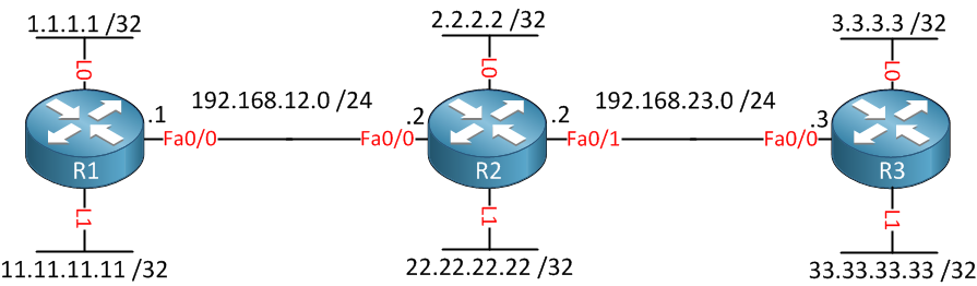
Above we have 3 routers, and each router has 2 loopback interfaces so that we have plenty of networks to play with. Before we enable MPLS, we’ll configure OSPF so that all networks are advertised:
R1,R2,R3:
(config)#router ospf 1
(config-router)#network 0.0.0.0 255.255.255.255 area 0
We’ll do this the easy way and activate OSPF on all interfaces. Now let’s enable MPLS on the FastEthernet interfaces:
R1(config)#interface fastEthernet 0/0
R1(config-if)#mpls ipR2(config)#interface fastEthernet 0/0
R2(config-if)#mpls ip
R2(config-if)#exit
R2(config)#interface fastEthernet 0/1
R2(config-if)#mpls ipR3(config)#interface fastEthernet 0/0
R3(config-if)#mpls ipLet’s check if we have LDP neighbors:
R2#show mpls ldp neighbor | include Peer
    Peer LDP Ident: 11.11.11.11:0; Local LDP Ident 22.22.22.22:0
    Peer LDP Ident: 33.33.33.33:0; Local LDP Ident 22.22.22.22:0
So far, so good. Now let’s take a look at the LDP labels that have been generated:
R1#show mpls forwarding-table
Local  Outgoing    Prefix            Bytes tag  Outgoing   Next Hop
tag    tag or VC   or Tunnel Id      switched   interface
16     Pop tag     2.2.2.2/32        0          Fa0/0      192.168.12.2
17     17          33.33.33.33/32    0          Fa0/0      192.168.12.2
18     18          3.3.3.3/32        0          Fa0/0      192.168.12.2
19     Pop tag     22.22.22.22/32    0          Fa0/0      192.168.12.2
20 Pop tag 192.168.23.0/24 0 Fa0/0 192.168.12.2R2#show mpls forwarding-table
Local Outgoing Prefix Bytes tag Outgoing Next Hop
tag tag or VC or Tunnel Id switched interface
16 Pop tag 1.1.1.1/32 0 Fa0/0 192.168.12.1
17 Pop tag 33.33.33.33/32 0 Fa0/1 192.168.23.3
18 Pop tag 3.3.3.3/32 0 Fa0/1 192.168.23.3
19 Pop tag 11.11.11.11/32 0 Fa0/0 192.168.12.1R3#show mpls forwarding-table
Local Outgoing Prefix Bytes tag Outgoing Next Hop
tag tag or VC or Tunnel Id switched interface
16 Pop tag 192.168.12.0/24 0 Fa0/0 192.168.23.2
17 16 1.1.1.1/32 0 Fa0/0 192.168.23.2
18 Pop tag 2.2.2.2/32 0 Fa0/0 192.168.23.2
19 Pop tag 22.22.22.22/32 0 Fa0/0 192.168.23.2
20 19 11.11.11.11/32 0 Fa0/0 192.168.23.2For all networks, a label has been generated by LDP. Now let’s configure filtering to only generate labels for the loopback 0 interfaces. This is how you do it:
R1(config)#access-list 1 permit 1.1.1.1 0.0.0.0
R1(config)#no mpls ldp advertise-labels
R1(config)#mpls ldp advertise-labels for 1R2(config)#access-list 1 permit 2.2.2.2 0.0.0.0
R2(config)#no mpls ldp advertise-labels
R2(config)#mpls ldp advertise-labels for 1R3(config)#access-list 1 permit 3.3.3.3 0.0.0.0
R3(config)#no mpls ldp advertise-labels
R3(config)#mpls ldp advertise-labels for 1First, use no mpls ldp advertise-labels to disable the advertisement of all labels. Secondly, use the mpls ldp advertise-labels for command and refer to an access-list or prefix-list to choose what networks should have a label.
no mpls ldp advertise-labelscommand, you will discover that LDP is STILL advertising a label for each network…Let’s verify our work:
R1#show mpls forwarding-table
Local  Outgoing    Prefix            Bytes tag  Outgoing   Next Hop
tag    tag or VC   or Tunnel Id      switched   interface
16     Pop tag     2.2.2.2/32        0          Fa0/0      192.168.12.2
17     Untagged    33.33.33.33/32    0          Fa0/0      192.168.12.2
18     Untagged    3.3.3.3/32        0          Fa0/0      192.168.12.2
19     Untagged    22.22.22.22/32    0          Fa0/0      192.168.12.2
20 Untagged 192.168.23.0/24 0 Fa0/0 192.168.12.2R2#show mpls forwarding-table
Local Outgoing Prefix Bytes tag Outgoing Next Hop
tag tag or VC or Tunnel Id switched interface
16 Pop tag 1.1.1.1/32 0 Fa0/0 192.168.12.1
17 Untagged 33.33.33.33/32 0 Fa0/1 192.168.23.3
18 Pop tag 3.3.3.3/32 0 Fa0/1 192.168.23.3
19 Untagged 11.11.11.11/32 0 Fa0/0 192.168.12.1R3#show mpls forwarding-table
Local Outgoing Prefix Bytes tag Outgoing Next Hop
tag tag or VC or Tunnel Id switched interface
16 Untagged 192.168.12.0/24 0 Fa0/0 192.168.23.2
17 Untagged 1.1.1.1/32 0 Fa0/0 192.168.23.2
18 Pop tag 2.2.2.2/32 0 Fa0/0 192.168.23.2
19 Untagged 22.22.22.22/32 0 Fa0/0 192.168.23.2
20 Untagged 11.11.11.11/32 0 Fa0/0 192.168.23.2Above, you can see that only networks 1.1.1.1/32, 2.2.2.2/32, and 3.3.3.3/32 now have a label when advertised to an LDP neighbor.
For r1 why is 3.3.3.3 untagged?
Similar for r3 why is 1.1.1.1 untagged?
That’s what this tutorial is about…filtering tags so not all prefixes get a tag. R2 only sends a tag for 2.2.2.2 /32 to R1 and R3, not for 1.1.1.1/32 or 3.3.3.3/32.
My bad. Just realized that r2 is between r1 and r3
Rene,
Great lesson as usual. However, I have question loop backs which are not label it means they can not be reached and can not be in the routing table?
Thanks
Hamoood
Hi Hamood,
If there is no label for a prefix then we can still reach it through normal routing with the routing table, the only difference is that it won’t be label switched.
Rene