Lesson Contents
In a previous lesson I explained how we can use VRF lite to create multiple virtual routing tables. EVN (Easy Virtual Network) has some “enhancements” to make configuration and management of VRF lite a bit simpler. Let’s take a look at an example topology:
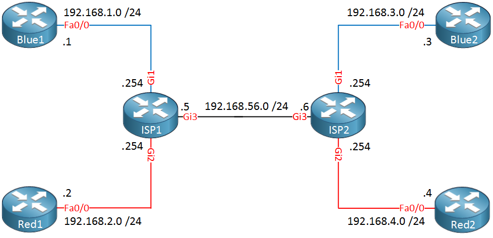
In the picture above we have two ISP routers and two customers, one called “Blue” and another one called “Red”. The blue and red lines indicate the VRFs that we use.When we use VRF lite we have to configure sub-interfaces for each VRF on the Gigabit3 interfaces of ISP1 and ISP2. Each sub-interface belongs to a different VRF and uses 802.1Q encapsulation to differentiate the different VRFs.
When you have many VRFs it might be a bit annoying to have many sub-interfaces. To simplify the configuration, EVN uses something called a VNET Trunk:
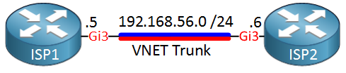
Instead of using sub-interfaces, we define the interfaces between the two ISP routers as a VNET Trunk. EVN will automatically create sub-interfaces for each VRF for us, I’ll show you this in a bit.
Let’s take a look at the configuration.
Basic EVN Configuration
We’ll use the topology above for the configuration example. I will start with ISP1 and first I will create two VRFs…one for each customer:
ISP1(config)#vrf definition Blue
ISP1(config-vrf)#vnet tag 10
ISP1(config-vrf)#address-family ipv4ISP1(config)#vrf definition Red
ISP1(config-vrf)#vnet tag 20
ISP1(config-vrf)#address-family ipv4The vnet tag command is something new. This identifies the vrf and when our VRF traffic crosses the VNET Trunk, it will use this number as the tag for 802.1Q. Let’s add the interfaces to the correct VRF:
ISP1(config)#interface GigabitEthernet 1
ISP1(config-if)#vrf forwarding Blue
ISP1(config-if)#ip address 192.168.1.254 255.255.255.0ISP1(config)#interface GigabitEthernet 2
ISP1(config-if)#vrf forwarding Red
ISP1(config-if)#ip address 192.168.2.254 255.255.255.0This takes care of the interfaces of the ISP1 router, let’s configure the two customer routers that are connected to the ISP1 router as well:
Blue1(config)#interface FastEthernet 0/0
Blue1(config-if)#ip address 192.168.1.1 255.255.255.0Red1(config)#interface FastEthernet 0/0
Red1(config-if)#ip address 192.168.2.2 255.255.255This takes care of the VRF configuration. We’ll do something similar on ISP2:
ISP2(config)#vrf definition Blue
ISP2(config-vrf)#vnet tag 10
ISP2(config-vrf)#address-family ipv4ISP2(config)#vrf definition Red
ISP2(config-vrf)#vnet tag 20
ISP2(config-vrf)#address-family ipv4ISP2(config)#interface GigabitEthernet 1
ISP2(config-if)#vrf forwarding Blue
ISP2(config-if)#ip address 192.168.3.254 255.255.255.0
ISP2(config)#interface GigabitEthernet 2
ISP2(config-if)#vrf forwarding Red
ISP2(config-if)#ip address 192.168.4.254 255.255.255.0And the two customer routers on the right side of ISP2:
Blue2(config)#interface FastEthernet 0/0
Blue2(config-if)#ip address 192.168.3.3 255.255.255.0Red2(config)#interface FastEthernet 0/0
Red2(config-if)#ip address 192.168.4.4 255.255.255.0The VRF configuration is now finished with the exception of the trunk in between ISP1 and ISP2. It might be a good idea to verify that the VRFs are working before we continue:
ISP1#show vrf
  Name                             Default RD            Protocols   Interfaces
  Blue                             <not set>             ipv4        Gi1
  Red                              <not set>             ipv4        Gi2
First we check if the VRFs are available and what interfaces are assigned to them. Let’s see if ISP1 can ping router Blue1 and Red1:
ISP1#ping vrf Blue 192.168.1.1
Type escape sequence to abort.
Sending 5, 100-byte ICMP Echos to 192.168.1.1, timeout is 2 seconds:
!!!!!
Success rate is 100 percent (5/5), round-trip min/avg/max = 2/2/3 msISP1#ping vrf Red 192.168.2.2
Type escape sequence to abort.
Sending 5, 100-byte ICMP Echos to 192.168.2.2, timeout is 2 seconds:
!!!!!
Success rate is 100 percent (5/5), round-trip min/avg/max = 2/2/3 msNo problem at all, at least we know the VRFs are working on ISP1. Let’s check ISP2 as well:
ISP2#show vrf
  Name                             Default RD            Protocols   Interfaces
  Blue                             <not set>             ipv4        Gi1
  Red                              <not set>             ipv4        Gi2
Let’s ping the Blue2 and Red2 routers, see if they respond:
ISP2#ping vrf Blue 192.168.3.3
Type escape sequence to abort.
Sending 5, 100-byte ICMP Echos to 192.168.3.3, timeout is 2 seconds:
!!!!!
Success rate is 100 percent (5/5), round-trip min/avg/max = 2/2/3 msISP2#ping vrf Red 192.168.4.4
Type escape sequence to abort.
Sending 5, 100-byte ICMP Echos to 192.168.4.4, timeout is 2 seconds:
!!!!!
Success rate is 100 percent (5/5), round-trip min/avg/max = 2/2/3 msWe just verified that the VRF configuration on ISP1 and ISP2 is working as expected. Let’s continue with the VNET trunk configuration:
ISP1(config)#interface GigabitEthernet3
ISP1(config-if)#vnet trunk
ISP1(config-if)#ip address 192.168.56.5 255.255.255.0ISP2(config)#interface GigabitEthernet3
ISP2(config-if)#vnet trunk
ISP2(config-if)#ip address 192.168.56.6 255.255.255.0That’s all we have to do…use the vnet trunk command to tell the routers that we want to use this interface, that’s it. Behind the scenes is where the “EVN magic” happens. Take a look at the running configuration of one of the ISP routers:
ISP1#show running-config interface GigabitEthernet3
Building configuration...

Current configuration : 103 bytes
!
interface GigabitEthernet3
 vnet trunk
 ip address 192.168.56.5 255.255.255.0
 negotiation auto
end
This is what we just configured, there’s not much on the interface. In reality however this is what the configuration looks like:
ISP1#show derived-config | begin GigabitEthernet3
interface GigabitEthernet3
 vnet trunk
 ip address 192.168.56.5 255.255.255.0
 negotiation auto
!
interface GigabitEthernet3.10
 description Subinterface for VNET Blue
 encapsulation dot1Q 10
 vrf forwarding Blue
 ip address 192.168.56.5 255.255.255.0
!
interface GigabitEthernet3.20
 description Subinterface for VNET Red
 encapsulation dot1Q 20
 vrf forwarding Red
 ip address 192.168.56.5 255.255.255.0
EVN automatically created two sub-interfaces for us for each VRF. You can see that it uses 802.1Q encapsulation and the tag is based on the vnet tag that we configured earlier. Every time you create a new VRF, EVN will automatically create the required sub-interface.
There are a couple of other EVN “tricks” but to show them we’ll have to configure some routing.
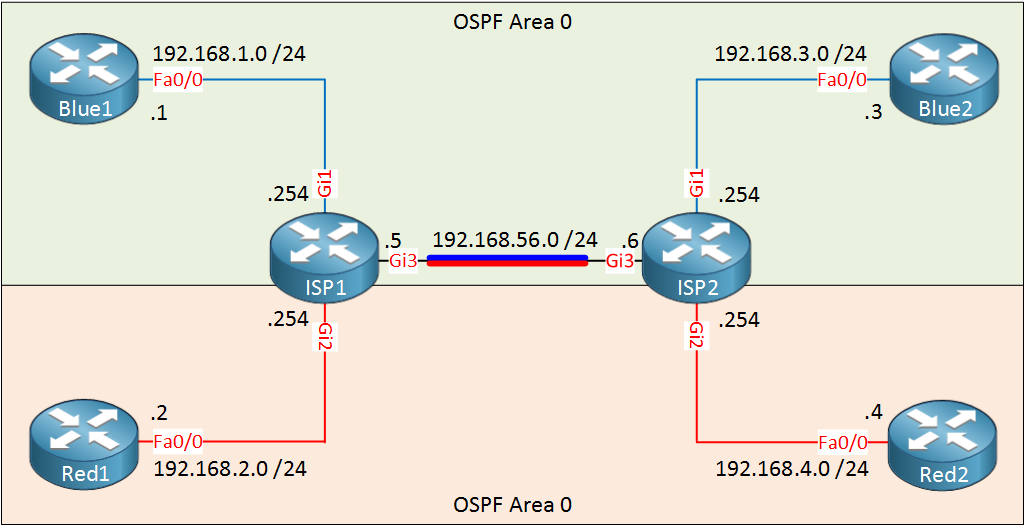
Routing Configuration
Let’s configure OSPF within VRF Blue so that Blue1/Blue2 are able to reach each other. We’ll do the same thing for VRF Red so that Red1/Red2 can reach each other. This is what the topology looks like:
Let’s configure OSPF for VRF Blue first:
Blue1(config)#router ospf 1
Blue1(config-router)#network 192.168.1.0 0.0.0.255 area 0Blue2(config)#router ospf 1
Blue2(config-router)#network 192.168.3.0 0.0.0.255 area 0ISP1(config)#router ospf 1 vrf Blue
ISP1(config-router)#network 192.168.1.0 0.0.0.255 area 0
ISP1(config-router)#network 192.168.56.0 0.0.0.255 area 0ISP2(config)#router ospf 1 vrf Blue
ISP2(config-router)#network 192.168.3.0 0.0.0.255 area 0
ISP2(config-router)#network 192.168.56.0 0.0.0.255 area 0Nothing special here, just regular OSPF. Let’s do the same thing for VRF Red:
Red1(config)#router ospf 1
Red1(config-router)#network 192.168.2.0 0.0.0.255 area 0Red2(config)#router ospf 1
Red2(config-router)#network 192.168.4.0 0.0.0.255 area 0ISP1(config)#router ospf 2 vrf Red
ISP1(config-router)#network 192.168.2.0 0.0.0.255 area 0
ISP1(config-router)#network 192.168.56.0 0.0.0.255 area 0ISP2(config)#router ospf 2 vrf Red
ISP2(config-router)#network 192.168.4.0 0.0.0.255 area 0
ISP2(config-router)#network 192.168.56.0 0.0.0.255 area 0That should take care of OSPF. Let’s verify our work:
Blue1#show ip route ospf

O     192.168.3.0/24 [110/3] via 192.168.1.254, 00:08:43, FastEthernet0/0
O 192.168.56.0/24 [110/2] via 192.168.1.254, 00:08:53, FastEthernet0/0Blue2#show ip route ospf
O 192.168.1.0/24 [110/3] via 192.168.3.254, 00:09:16, FastEthernet0/0
O 192.168.56.0/24 [110/2] via 192.168.3.254, 00:09:16, FastEthernet0/0Blue1 and Blue2 have learned about each others networks and the network in between ISP1 and ISP2. So far so good, let’s check the ISP routers:
ISP1#show ip route vrf Blue ospf

O 192.168.3.0/24 [110/2] via 192.168.56.6, 00:09:40, GigabitEthernet3.10ISP2#show ip route vrf Blue ospf
O 192.168.1.0/24 [110/2] via 192.168.56.5, 00:10:02, GigabitEthernet3.10This is looking good, no issues here. You can see the sub-interface of the VNET trunk here. Let’s check OSPF for VRF Red too:
Red1#show ip route ospf

O     192.168.4.0/24 [110/3] via 192.168.2.254, 00:03:26, FastEthernet0/0
O 192.168.56.0/24 [110/2] via 192.168.2.254, 00:03:36, FastEthernet0/0Red2#show ip route ospf
O 192.168.2.0/24 [110/3] via 192.168.4.254, 00:03:47, FastEthernet0/0
O 192.168.56.0/24 [110/2] via 192.168.4.254, 00:04:37, FastEthernet0/0Looking good, let’s check the ISP routers:
ISP1#show ip route vrf Red ospf

O 192.168.4.0/24 [110/2] via 192.168.56.6, 00:04:23, GigabitEthernet3.20ISP2#show ip route vrf Red ospf
O 192.168.2.0/24 [110/2] via 192.168.56.5, 00:04:54, GigabitEthernet3.20Everything is working as it should. With OSPF up and running we can play with EVN a bit more…
Route Replication (Shared Services)
VRFs are great because they allow us to separate routing information. Sometimes however we have some “shared services” that multiple VRFs could use. For example, maybe customer Blue and Red would like to use some central DNS or DHCP servers. You could have these servers within each VRF but it would be easier if we could share some central servers with multiple VRFs.
Route sharing between VRFs can be done with VRF Lite but it requires the configuration of RDs (Route Distinguishers) and BGP.
EVN supports route replication which “replicates” routes from one VRF to another. It doesn’t require RDs and BGP so the configuration is a bit simpler.
To share some services, we’ll create another VRF that we can use for our shared services. To demonstrate this I will create a new VRF called “Green” on ISP1. Take a look at the picture below:
Hi Rene,
You have uploaded Frame-Relay tutorial under EVN. Please re-upload the correct one.
Best Regards,
Ronnie
Hi Ronie,
You beat me to it…I published the post so I could link to it from the VRF lite post. Anyway I wrote it now and it’s online…hope you like it!
Rene
Hi Rene,
Really good explanation. VRF lite as DMVPN is new in CCNP route, so it’s good to learn about it. Thanks for your work.
However, are you going to update your CCNP books? Because I’d like to buy them, thanks to your straightforward explanation.
Regards,
Daniel B.
Hi Daniel,
Glad to hear you like it. The books are up-to-date btw, all 3 of them.
Rene
awesome i never thought i would understand EVN this easily..
i have one question Rene, on ISP1, when you show the route of RED and BLUE, it doesnt know the OSPF route to GREEN, but when you show the route of GREEN, it knows the route to RED and BLUE?
they all have the same config, you just route replicate from GREEN to BLUE and RED, then route replicate from BLUE and RED to GREEN. you still not use the redistribution but GREEN knows the OSPF route? whilst the BLUE and RED didnt know, thats why you ran the Redistribution process, so Red and BLUE now knows the ospf route to Green.