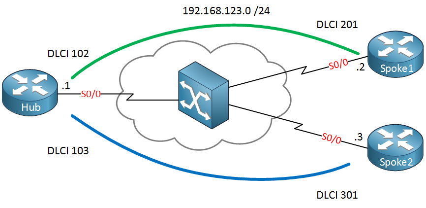
This time we’ll take a look at the configuration of frame-relay point-to-multipoint. If you have no idea what frame-relay is or what a PVC, DLCI, or LMI is you should start with my introduction to frame-relay first. Having said that, let’s have some fun with frame-relay! This is the topology we’ll use:

Above is the topology that we’ll use. Three routers in a hub and spoke model. There are two PVCs, and you can see the DLCI numbers in the picture. I’m using a single subnet (192.168.123.0 /24), so we will start with frame-relay point-to-multipoint.
Let’s prepare the interfaces:
Hub(config)#interface serial 0/0
Hub(config-if)#encapsulation frame-relaySpoke1(config)#interface serial 0/0
Spoke1(config-if)#encapsulation frame-relaySpoke2(config)#interface serial 0/0
Spoke2(config-if)#encapsulation frame-relayWe’ll change the encapsulation type to frame-relay for all interfaces. Let’s verify if our PVCs are working first:
Hub#show frame-relay pvc

PVC Statistics for interface Serial0/0 (Frame Relay DTE)

              Active     Inactive      Deleted       Static
  Local          2            0            0            0
  Switched       0            0            0            0
  Unused         0            0            0            0

DLCI = 102, DLCI USAGE = LOCAL, PVC STATUS = ACTIVE, INTERFACE = Serial0/0

  input pkts 12            output pkts 11           in bytes 1108
  out bytes 1074           dropped pkts 0           in pkts dropped 0
  out pkts dropped 0                out bytes dropped 0
  in FECN pkts 0           in BECN pkts 0           out FECN pkts 0
  out BECN pkts 0          in DE pkts 0             out DE pkts 0
  out bcast pkts 1         out bcast bytes 34
  5 minute input rate 0 bits/sec, 0 packets/sec
  5 minute output rate 0 bits/sec, 0 packets/sec
  pvc create time 00:15:37, last time pvc status changed 00:15:37

DLCI = 103, DLCI USAGE = LOCAL, PVC STATUS = ACTIVE, INTERFACE = Serial0/0

  input pkts 12            output pkts 11           in bytes 1108
  out bytes 1074           dropped pkts 0           in pkts dropped 0
  out pkts dropped 0                out bytes dropped 0
  in FECN pkts 0           in BECN pkts 0           out FECN pkts 0
  out BECN pkts 0          in DE pkts 0             out DE pkts 0
  out bcast pkts 1         out bcast bytes 34
  5 minute input rate 0 bits/sec, 0 packets/sec
  5 minute output rate 0 bits/sec, 0 packets/sec
  pvc create time 00:15:41, last time pvc status changed 00:15:41
The show frame-relay pvc command tells us that the PVCs are active. You can also see the DLCI numbers this way. This tells us that layer 2 of our frame-relay is working. In case of trouble, it might be a good idea to verify LMI:
Hub#show frame-relay lmi

LMI Statistics for interface Serial0/0 (Frame Relay DTE) LMI TYPE = ANSI
  Invalid Unnumbered info 0		Invalid Prot Disc 0
  Invalid dummy Call Ref 0		Invalid Msg Type 0
  Invalid Status Message 0		Invalid Lock Shift 0
  Invalid Information ID 0		Invalid Report IE Len 0
  Invalid Report Request 0		Invalid Keep IE Len 0
  Num Status Enq. Sent 147		Num Status msgs Rcvd 148
  Num Update Status Rcvd 0		Num Status Timeouts 0
  Last Full Status Req 00:00:35		Last Full Status Rcvd 00:00:35
Use show frame-relay lmi to see the LMI information. It tells us that we are currently using the ANSI type. It doesn’t matter which one you use as long as it’s the same on all routers.
Since layer two is working, we’ll configure some IP addresses and see if we can get layer three working:
Hub(config)#interface serial 0/0
Hub(config-if)#ip address 192.168.123.1Spoke1(config)#interface serial 0/0
Spoke1(config-if)#ip address 192.168.123.2Spoke2(config)#interface serial 0/0
Spoke2(config-if)#ip address 192.168.123.3Let’s see if we can reach the other side:
Hub#ping 192.168.123.2

Type escape sequence to abort.
Sending 5, 100-byte ICMP Echos to 192.168.123.2, timeout is 2 seconds:
!!!!!
Success rate is 100 percent (5/5), round-trip min/avg/max = 4/8/24 msHub#ping 192.168.123.3
Type escape sequence to abort.
Sending 5, 100-byte ICMP Echos to 192.168.123.3, timeout is 2 seconds:
!!!!!
Success rate is 100 percent (5/5), round-trip min/avg/max = 1/4/8 msAs you can see, the hub router can reach both spoke routers. This is because Inverse ARP is enabled by default.
We can check the frame-relay maps to confirm this:
Hub#show frame-relay map
Serial0/0 (up): ip 192.168.123.2 dlci 102(0x66,0x1860), dynamic,
              broadcast,, status defined, active
Serial0/0 (up): ip 192.168.123.3 dlci 103(0x67,0x1870), dynamic,
broadcast,, status defined, activeSpoke1#show frame-relay map
Serial0/0 (up): ip 192.168.123.1 dlci 201(0xC9,0x3090), dynamic,
broadcast,, status defined, activeSpoke2#show frame-relay map
Serial0/0 (up): ip 192.168.123.1 dlci 301(0x12D,0x48D0), dynamic,
broadcast,, status defined, activeAbove, you see the mappings between the IP address and the DLCI number. There are two other interesting things to see here. The keyword dynamic means that the entry was learned because of inverse ARP. The keyword broadcast means we can send broadcast or multicast through our PVC.
Configurations
Want to take a look for yourself? Here you will find the final configuration of each device.
Hub
hostname Hub
!
interface Serial0/0
 ip address 192.168.123.1 255.255.255.0
 encapsulation frame-relay
!
end
Spoke1
hostname Spoke1
!
interface Serial0/0
 ip address 192.168.123.2 255.255.255.0
 encapsulation frame-relay
!
end
Spoke2
hostname Spoke2
!
interface Serial0/0
 ip address 192.168.123.3 255.255.255.0
 encapsulation frame-relay
!
end
Let’s disable Inverse ARP and create some mappings ourselves:


Thanks it were really helpful information.
many thanks for the article; however the spoke-spoke mappings at the end of the article are not correct and we need a new DLCI mapping other than the one already used
If I use the mappings defined here, when pinging from Spoke1-Spoke2 (and vice verca) I get UUUUU. Changing the mappings to 2:221-3:321 on the switch and the spoke configs solved the problem
Spoke1 - frame-relay map ip 192.168.123.3 221
Spoke 2 - frame-relay map ip 192.168.123.2 321
Hi Usman,
In your case you added another PVC between Spoke1 and Spoke2 which will work but it’s not required.
My example above is a hub and spoke example, if your mappings are correct you can ping between Spoke1 and Spoke2 through the hub router.
Rene
thanks for the clarification. It does work now
Glad to hear you got it working.