Lesson Contents
Policy-based routing can be used to change the next hop IP address for traffic matching certain criteria. This can be useful to overrule your routing table for certain traffic types. I will show you how to configure policy based routing.
Configuration
here’s the topology that we will use:
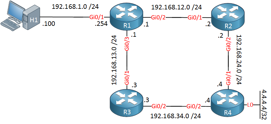
Take a look at the topology picture above. OSPF is configured on all routers. Since we are using Gigabit interfaces everywhere, traffic from R1 destined to 4.4.4.4 would normally be load balanced between R2 and R3. However, I changed the cost on the Gigabit Ethernet 0/3 interface of R1 so that all traffic will go from R1 > R2 > R4.
Configurations
Want to try this for yourself? Here you will find the startup configuration of each device.
H1
hostname H1
!
no ip routing
!
no ip cef
!
interface GigabitEthernet0/1
 ip address 192.168.1.100 255.255.255.0
!
ip default-gateway 192.168.1.254
!
end
R1
hostname R1
!
ip cef
!
interface GigabitEthernet0/1
 ip address 192.168.1.254 255.255.255.0
!
interface GigabitEthernet0/2
 ip address 192.168.12.1 255.255.255.0
!
interface GigabitEthernet0/3
 ip address 192.168.13.1 255.255.255.0
 ip ospf cost 1000
!
router ospf 1
 network 192.168.1.0 0.0.0.255 area 0
 network 192.168.12.0 0.0.0.255 area 0
 network 192.168.13.0 0.0.0.255 area 0
!
end
R2
hostname R2
!
ip cef
!
interface GigabitEthernet0/1
 ip address 192.168.12.2 255.255.255.0
!
interface GigabitEthernet0/2
 ip address 192.168.24.2 255.255.255.0
!
router ospf 1
 network 192.168.12.0 0.0.0.255 area 0
 network 192.168.24.0 0.0.0.255 area 0
!
end
R3
hostname R3
!
ip cef
!
interface GigabitEthernet0/0
 no ip address
!
interface GigabitEthernet0/1
 ip address 192.168.13.3 255.255.255.0
!
interface GigabitEthernet0/2
 ip address 192.168.34.3 255.255.255.0
!
router ospf 1
 network 192.168.13.0 0.0.0.255 area 0
 network 192.168.34.0 0.0.0.255 area 0
!
end
R4
hostname R4
!
ip cef
!
interface Loopback0
 ip address 4.4.4.4 255.255.255.255
!
interface GigabitEthernet0/1
 ip address 192.168.24.4 255.255.255.0
!
interface GigabitEthernet0/2
 ip address 192.168.34.4 255.255.255.0
!
router ospf 1
 network 4.4.4.4 0.0.0.0 area 0
 network 192.168.24.0 0.0.0.255 area 0
 network 192.168.34.0 0.0.0.255 area 0
!
end
Let’s verify this:
R1#show ip ospf interface GigabitEthernet 0/2 | include Cost:
Process ID 1, Router ID 192.168.13.1, Network Type BROADCAST, Cost: 1R1#show ip ospf interface GigabitEthernet 0/3 | include Cost:
Process ID 1, Router ID 192.168.13.1, Network Type BROADCAST, Cost: 1000Above you can see the increased cost. Let’s try a quick traceroute from H1:
H1#traceroute 4.4.4.4 probe 1
Type escape sequence to abort.
Tracing the route to 4.4.4.4
VRF info: (vrf in name/id, vrf out name/id)
  1 192.168.1.254 7 msec
  2 192.168.12.2 6 msec
  3 192.168.24.4 8 msec
Now let’s say I want to use the link between R1 and R3 to reach 4.4.4.4. I could influence the metric for OSPF, but this applies to all traffic. What if I wanted to use this link for certain traffic only?
We could use the link between R1/R2 for the majority of our traffic and use the link between R1/R3 only for certain traffic. This can be very useful. For example, imagine that the link between R1/R3 is a dedicated link that offers QoS for VoIP traffic.
This is something we can achieve with PBR (Policy Based Routing). Let me show you how!
Right now, all traffic is sent toward R2:
R1#show ip route | include 4.4.4.4
O        4.4.4.4 [110/3] via 192.168.12.2, 00:16:48, GigabitEthernet0/2
Now let’s say that we want all ICMP traffic from H1 destined for 4.4.4.4 to cross the link between R1/R3. Here’s how to do this:
R1(config)#ip access-list extended ICMP_H1
R1(config-ext-nacl)#permit icmp host 192.168.1.100 host 4.4.4.4
First, I create an access-list that matches my traffic. Now we have to create a route-map:
R1(config)#route-map PBR_H1 permit 10
R1(config-route-map)#match ip address ICMP_H1
R1(config-route-map)#set ip next-hop 192.168.13.3
Whenever the traffic matches the access-list, we will change the next hop to 192.168.13.3 (R3).
Last but not least, let’s activate it:
R1(config)#interface GigabitEthernet 0/1
R1(config-if)#ip policy route-map PBR_H1
Let’s see if it works. To see it in action, I will enable a debug on R1:
R1#debug ip policy
Policy routing debugging is on
Now let’s send a ping from H1:
H1#ping 4.4.4.4 repeat 1
Type escape sequence to abort.
Sending 1, 100-byte ICMP Echos to 4.4.4.4, timeout is 2 seconds:
!
Success rate is 100 percent (1/1), round-trip min/avg/max = 13/13/13 ms
The ping is working. Let’s see what R1 thinks of it:
R1#
IP: s=192.168.1.100 (GigabitEthernet0/1), d=4.4.4.4, len 100, FIB policy match
IP: s=192.168.1.100 (GigabitEthernet0/1), d=4.4.4.4, len 100, PBR_H1 Counted
IP: s=192.168.1.100 (GigabitEthernet0/1), d=4.4.4.4, g=192.168.13.3, len 100, FIB policy routed
Above, you can see that it has been policy routed towards 192.168.13.3. We can also verify this by looking at the route-map:
R1#show route-map PBR_H1
route-map PBR_H1, permit, sequence 10
  Match clauses:
    ip address (access-lists): ICMP_H1
  Set clauses:
    ip next-hop 192.168.13.3
Nexthop tracking current: 0.0.0.0
192.168.13.3, fib_nh:0,oce:0,status:0

  Policy routing matches: 1 packets, 114 bytes
Let’s try some traffic that doesn’t match our access-list. Telnet, for example:
H1#telnet 4.4.4.4
Trying 4.4.4.4 ... Open
H1 can connect but it’s not policy routed:
R1#
IP: s=192.168.1.100 (GigabitEthernet0/1), d=4.4.4.4, len 40, FIB policy rejected(no match) - normal forwarding
As you can see above, this telnet traffic is routed using the normal path.
There is one more thing I’d like to show you. With policy-based routing, there is a difference between traffic going through the router and traffic originating from the router.
The example above is for traffic that went through our router. What if we want to policy route traffic that originated from R1? We will have to use another command to activate it. Let’s create another route-map:
R1(config)#ip access-list extended ICMP_R1
R1(config-ext-nacl)#permit icmp host 192.168.12.1 host 4.4.4.4
R1(config-ext-nacl)#permit icmp host 192.168.13.1 host 4.4.4.4

R1(config)#route-map PBR_R1 permit 10
R1(config-route-map)#match ip address ICMP_R1
R1(config-route-map)#set ip next-hop 192.168.13.3
The route-map above will redirect all traffic from R1 to 4.4.4.4 toward R3. To activate this, we need to use another command:
R1(config)#ip local policy route-map PBR_R1This time, we need to use the ip local policy command. Let’s test this:
R1#ping 4.4.4.4 repeat 1
Type escape sequence to abort.
Sending 1, 100-byte ICMP Echos to 4.4.4.4, timeout is 2 seconds:
!
Success rate is 100 percent (1/1), round-trip min/avg/max = 19/19/19 ms
R1#
IP: s=192.168.12.1 (local), d=4.4.4.4, len 100, policy match
IP: route map PBR_R1, item 10, permit
IP: s=192.168.12.1 (local), d=4.4.4.4 (GigabitEthernet0/3), len 100, policy routed
IP: local to GigabitEthernet0/3 192.168.13.3Great, our traffic from R1 is policy routed.
Hi Rene,
I tried to do the above lab; however been getting policy-rejected error.Below is the output
... Continue reading in our forumHi Pramod,
Your configuration looks ok, the strange thing is that the first packet matches but the second one doesn’t? What hardware are you using for this?
Here’s an example when I configure and debug it:
... Continue reading in our forumHi Rene - I’ am on C2691-adventerprisek9-mz.124-25c let me know if you suggest for any other IOS.
Hmm that is one of the latest IOS images for that platform I think. You might want to try it on a 3725 in GNS3, that works for sure.
Hi Rene,
I have a question and it’s not in any of the subjects, maybe you can answer it.
... Continue reading in our forumI have a router with 2 interfaces:
G0/1–> ip address 172.16.254.6/30, G0/2–> 172.16.254.2/30, running OSPF. G0/1 Connects to my MASTER firewall with ip add 172.16.254.1/30 and G0/2 connects to my SECONDARY firewall with ip address 172.16.254.1, the firewalls are configure HA. If I try to configure G0/2 with an ip add of 172.16.254.3 it gives me an error. How can I make this scenario work with the 2 interfaces and the firewalls? or Do I need to get a switch module with 2 in