Lesson Contents
The OSPF point-to-point network type is designed for networks where only two routers are directly connected, such as serial links, PPP connections, GRE, or dedicated Ethernet links between two devices. With this network type, OSPF will use multicast for hello packets but will not perform a DR/BDR election. OSPF automatically detects network types based on the underlying media. However, we can manually configure different network types if required.
Configuration
We will configure OSPF with a point-to-point network type over Ethernet. Here is the topology we’ll use:
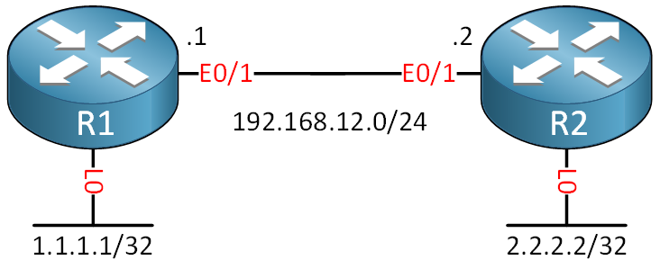
I use a direct Ethernet connection between the two routers to demonstrate this. This is common in scenarios where you have dedicated links between two routers and want to avoid DR/BDR elections on multi-access networks. I’ll show the OSPF packets so you can see it uses multicast hello packets. I use Cisco IOS Software [Dublin], Linux Software (X86_64BI_LINUX-ADVENTERPRISEK9-M), Version 17.12.1, RELEASE SOFTWARE (fc5) for this example.
Configurations
Want to take a look for yourself? Here you will find the final configuration of each device.
R1
hostname R1
!
interface Loopback0
 ip address 1.1.1.1 255.255.255.255
!
interface Ethernet0/1
 ip address 192.168.12.1 255.255.255.0
!
end
R2
hostname R2
!
interface Loopback0
 ip address 2.2.2.2 255.255.255.255
!
interface Ethernet0/1
 ip address 192.168.12.2 255.255.255.0
!
end
We start by changing the network type on all interfaces to point-to-point:
R1(config)#interface Ethernet0/1
R1(config-if)#ip ospf network point-to-pointR2(config)#interface Ethernet0/1
R2(config-if)#ip ospf network point-to-pointNext, let’s add all required network commands:
R1(config)#router ospf 1
R1(config-router)#router-id 1.1.1.1
R1(config-router)#network 192.168.12.0 0.0.0.255 area 0
R1(config-router)#network 1.1.1.1 0.0.0.0 area 0R2(config)#router ospf 1
R2(config-router)#router-id 2.2.2.2
R2(config-router)#network 192.168.12.0 0.0.0.255 area 0
R2(config-router)#network 2.2.2.2 0.0.0.0 area 0Since point-to-point networks support multicast and only have two routers, we don’t need to configure neighbors manually. OSPF will automatically discover the neighbor using multicast hello packets. That’s all we need to configure.
Verification
Let’s verify our configuration. First, let’s check the OSPF network type on R1:
R1#show ip ospf interface Ethernet0/1
  Ethernet0/1 is up, line protocol is up
  Internet Address 192.168.12.1/24, Interface ID 3, Area 0
  Attached via Network Statement
  Process ID 1, Router ID 1.1.1.1, Network Type POINT_TO_POINT, Cost: 10
  Topology-MTID    Cost    Disabled    Shutdown      Topology Name
        0           10        no          no            Base
  Transmit Delay is 1 sec, State POINT_TO_POINT
  Timer intervals configured, Hello 10, Dead 40, Wait 40, Retransmit 5
    oob-resync timeout 40
    Hello due in 00:00:05
  Supports Link-local Signaling (LLS)
  Cisco NSF helper support enabled
  IETF NSF helper support enabled
  Can be protected by per-prefix Loop-Free FastReroute
  Can be used for per-prefix Loop-Free FastReroute repair paths
  Not Protected by per-prefix TI-LFA
  Index 1/1/1, flood queue length 0
  Next 0x0(0)/0x0(0)/0x0(0)
  Last flood scan length is 1, maximum is 1
  Last flood scan time is 0 msec, maximum is 0 msec
  Neighbor Count is 1, Adjacent neighbor count is 1
    Adjacent with neighbor 2.2.2.2
  Suppress hello for 0 neighbor(s)
In the output above, we see:
- The network type is point-to-point.
- The hello interval 10 seconds and dead interval 40 seconds.
- State: POINT-TO-POINT (no DR/BDR election).
- No priority is shown since there’s no DR/BDR election.
Let’s verify the network type on R2 as well:
R2#show ip ospf interface Ethernet0/1 | include Network Type
  Process ID 1, Router ID 2.2.2.2, Network Type POINT_TO_POINT, Cost: 10
This looks good. Let’s check our automatically discovered neighbor:
R1#show ip ospf neighbor

Neighbor ID     Pri   State           Dead Time   Address         Interface
2.2.2.2 0 FULL/ - 00:00:31 192.168.12.2 Ethernet0/1R2#show ip ospf neighbor
Neighbor ID Pri State Dead Time Address Interface
1.1.1.1 0 FULL/ - 00:00:32 192.168.12.1 Ethernet0/1We see that the neighbor adjacency is established. Notice that the priority is zero and there’s no DR/BDR designation, because point-to-point networks don’t elect a DR or BDR. When we enable a debug, we can see OSPF sends hello packets to the 224.0.0.5 multicast address:
R1#debug ip ospf hello
OSPF hello debugging is on

OSPF-1 HELLO Et0/1: Send hello to 224.0.0.5 area 0 from 192.168.12.1
OSPF-1 HELLO Et0/1: Rcv hello from 2.2.2.2 area 0 192.168.12.2
Here’s a capture of this hello packet:
Frame 12: 110 bytes on wire (880 bits), 110 bytes captured (880 bits) on interface eth1, id 0
Ethernet II, Src: aa:bb:cc:00:01:10 (aa:bb:cc:00:01:10), Dst: IPv4mcast_05 (01:00:5e:00:00:05)
Internet Protocol Version 4, Src: 192.168.12.1, Dst: 224.0.0.5
Open Shortest Path First
    OSPF Header
    OSPF Hello Packet
        Network Mask: 255.255.255.0
        Hello Interval [sec]: 10
        Options: 0x12, (L) LLS Data block, (E) External Routing
        Router Priority: 1
        Router Dead Interval [sec]: 40
        Designated Router: 0.0.0.0
        Backup Designated Router: 0.0.0.0
    OSPF LLS Data Block
Here you can see the multicast destination address 224.0.0.5. Here are all packets of this neighbor adjacency if you are interested:
Packet Capture: OSPF Network Type Point-to-Point over Ethernet
Let’s check if our routers learned something from each other: