Lesson Contents
OSPF automatically detects network types based on the underlying media. On Ethernet interfaces, OSPF defaults to network type broadcast. This network type assumes all routers on the segment can communicate directly with each other using multicast addresses. This means that OSPF will automatically discover neighbors and will do a DR/BDR election.
Configuration
Let’s take a closer look. Here is the topology we’ll use:
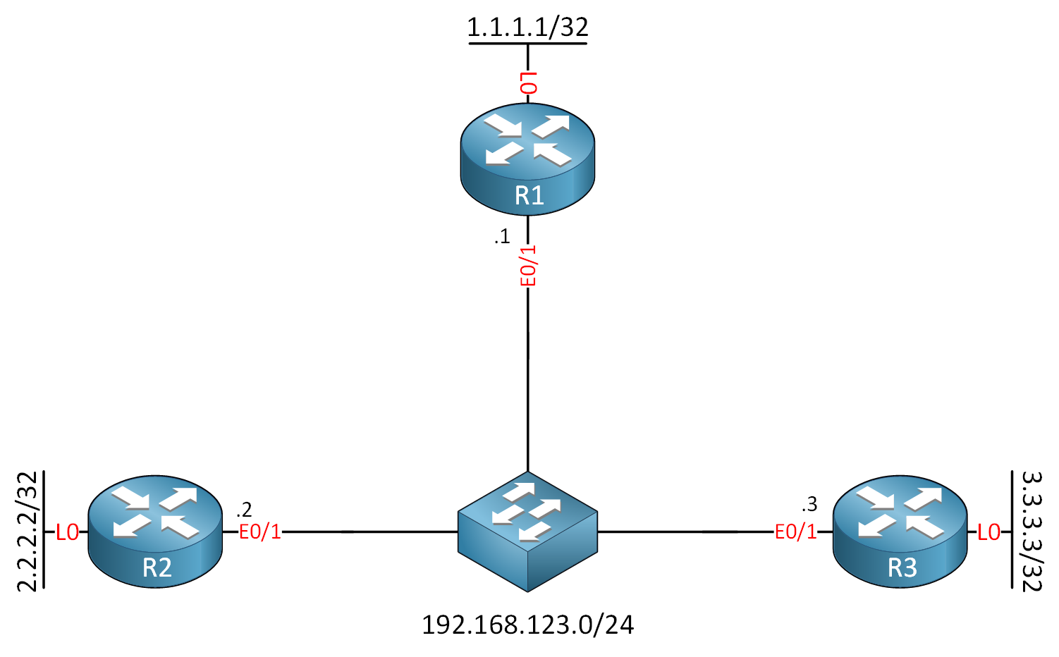
We have three routers connected to a switch in the same subject. Each router has a loopback interface, so we have something to advertise. I use Cisco IOS Software [Dublin], Linux Software (X86_64BI_LINUX-ADVENTERPRISEK9-M), Version 17.12.1, RELEASE SOFTWARE (fc5) for this example.
Configurations
Want to take a look for yourself? Here you will find the startup configuration of each device.
R1
hostname R1
!
interface Loopback0
 ip address 1.1.1.1 255.255.255.255
!
interface Ethernet0/1
 ip address 192.168.123.1 255.255.255.0
!
end
R2
hostname R2
!
interface Loopback0
 ip address 2.2.2.2 255.255.255.255
!
interface Ethernet0/1
 ip address 192.168.123.2 255.255.255.0
!
end
R3
hostname R3
!
interface Loopback0
 ip address 3.3.3.3 255.255.255.255
!
interface Ethernet0/1
 ip address 192.168.123.3 255.255.255.0
!
end
Let’s configure OSPF and advertise the loopback interfaces:
R1(config)#router ospf 1
R1(config-router)#router-id 1.1.1.1
R1(config-router)#network 192.168.123.0 0.0.0.255 area 0
R1(config-router)#network 1.1.1.1 0.0.0.0 area 0R2(config)#router ospf 1
R2(config-router)#router-id 2.2.2.2
R2(config-router)#network 192.168.123.0 0.0.0.255 area 0
R2(config-router)#network 1.1.1.1 0.0.0.0 area 0R3(config)#router ospf 1
R3(config-router)#router-id 3.3.3.3
R3(config-router)#network 192.168.123.0 0.0.0.255 area 0
R3(config-router)#network 3.3.3.3 0.0.0.0 area 0That’s all we need to configure.
Verification
Let’s verify our work. First, let’s check the OSPF network type:
R1#show ip ospf interface Ethernet0/1
Ethernet0/1 is up, line protocol is up
  Internet Address 192.168.123.1/24, Interface ID 3, Area 0
  Attached via Network Statement
  Process ID 1, Router ID 1.1.1.1, Network Type BROADCAST, Cost: 10
  Topology-MTID    Cost    Disabled    Shutdown      Topology Name
        0           10        no          no            Base
  Transmit Delay is 1 sec, State DROTHER, Priority 1
  Designated Router (ID) 3.3.3.3, Interface address 192.168.123.3
  Backup Designated router (ID) 3.3.3.3, Interface address 192.168.123.3
  Timer intervals configured, Hello 10, Dead 40, Wait 40, Retransmit 5
    oob-resync timeout 40
    Hello due in 00:00:07
  Supports Link-local Signaling (LLS)
  Cisco NSF helper support enabled
  IETF NSF helper support enabled
  Can be protected by per-prefix Loop-Free FastReroute
  Can be used for per-prefix Loop-Free FastReroute repair paths
  Not Protected by per-prefix TI-LFA
  Index 1/1/1, flood queue length 0
  Next 0x0(0)/0x0(0)/0x0(0)
  Last flood scan length is 1, maximum is 1
  Last flood scan time is 0 msec, maximum is 0 msec
  Neighbor Count is 2, Adjacent neighbor count is 1
    Adjacent with neighbor 3.3.3.3  (Designated Router)
  Suppress hello for 0 neighbor(s)
As you can see, the network type is set to broadcast. This output also shows the default timers:
- Hello interval: 10 seconds
- Dead interval: 40 seconds
The priority used for the DR/BDR election is one by default. Let’s check the network type on R2 and R3:
R2#show ip ospf interface Ethernet0/1 | include Network Type
Process ID 1, Router ID 2.2.2.2, Network Type BROADCAST, Cost: 10R3#show ip ospf interface Ethernet0/1 | include Network Type
Process ID 1, Router ID 3.3.3.3, Network Type BROADCAST, Cost: 10This is the same as on R1. Let’s check the neighbor adjacencies:
R1#show ip ospf neighbor

Neighbor ID     Pri   State           Dead Time   Address         Interface
2.2.2.2           1   FULL/BDR        00:00:31    192.168.123.2   Ethernet0/1
3.3.3.3 1 FULL/DR 00:00:37 192.168.123.3 Ethernet0/1R2#show ip ospf neighbor
Neighbor ID Pri State Dead Time Address Interface
1.1.1.1 1 FULL/DROTHER 00:00:39 192.168.123.1 Ethernet0/1
3.3.3.3 1 FULL/DR 00:00:39 192.168.123.3 Ethernet0/1R3#show ip ospf neighbor
Neighbor ID Pri State Dead Time Address Interface
1.1.1.1 1 FULL/DROTHER 00:00:39 192.168.123.1 Ethernet0/1
2.2.2.2 1 FULL/BDR 00:00:33 192.168.123.2 Ethernet0/1Each router has two neighbor adjacencies, and from this output, we can tell that R3 is the DR and R3 is the BDR. Let’s look at our hello packets:
R1#debug ip ospf hello
OSPF hello debugging is on

OSPF-1 HELLO Et0/1: Send hello to 224.0.0.5 area 0 from 192.168.123.1
This tells us that OSPF sends multicast hello packets. Here is the entire packet:
Frame 1: 118 bytes on wire (944 bits), 118 bytes captured (944 bits) on interface eth1, id 0
Ethernet II, Src: aa:bb:cc:00:01:10 (aa:bb:cc:00:01:10), Dst: IPv4mcast_05 (01:00:5e:00:00:05)
Internet Protocol Version 4, Src: 192.168.123.1, Dst: 224.0.0.5
Open Shortest Path First
    OSPF Header
    OSPF Hello Packet
        Network Mask: 255.255.255.0
        Hello Interval [sec]: 10
        Options: 0x12, (L) LLS Data block, (E) External Routing
        Router Priority: 1
        Router Dead Interval [sec]: 40
        Designated Router: 192.168.123.3
        Backup Designated Router: 192.168.123.2
        Active Neighbor: 2.2.2.2
        Active Neighbor: 3.3.3.3
    OSPF LLS Data Block
Here you can see all OSPF packets between the three routers:
Packet Capture: OSPF Network Type Broadcast over Ethernet
Let’s check some routes:
R1#show ip route ospf

      2.0.0.0/32 is subnetted, 1 subnets
O        2.2.2.2 [110/11] via 192.168.123.2, 00:00:10, Ethernet0/1
      3.0.0.0/32 is subnetted, 1 subnets
O        3.3.3.3 [110/11] via 192.168.123.3, 00:09:03, Ethernet0/1
R1 has learned the networks on the loopback interfaces. Because OSPF assumes direct connectivity to each neighbor, the next hop IP addresses for these networks are the IP addresses of R2 and R3. Let’s check the other two routers:
R2#show ip route ospf

      1.0.0.0/32 is subnetted, 1 subnets
O        1.1.1.1 [110/11] via 192.168.123.1, 00:09:14, Ethernet0/1
      3.0.0.0/32 is subnetted, 1 subnets
O 3.3.3.3 [110/11] via 192.168.123.3, 00:09:19, Ethernet0/1R3#show ip route ospf
1.0.0.0/32 is subnetted, 1 subnets
O 1.1.1.1 [110/11] via 192.168.123.1, 00:09:36, Ethernet0/1
2.0.0.0/32 is subnetted, 1 subnets
O 2.2.2.2 [110/11] via 192.168.123.2, 00:00:43, Ethernet0/1We see a similar output on these two routers. That’s all there is to it.
Hi Rene,
At the end of the reading, the config for R1 shows that it has non-broadcast network command issued, is this a typo for R1 config?
Hi @jom7132 ,
That’s a typo, yes, thanks, I got rid of it. It’s probably a leftover from when I labbed all these different network types.
Rene