If you studied Cisco’s CCNA you have learned that when you use OSPF all the areas have to be directly connected to the backbone area. Is this really true? Areas have to be connected to the backbone area but if they aren’t we can fix it with a virtual link.
Let me show you an example:
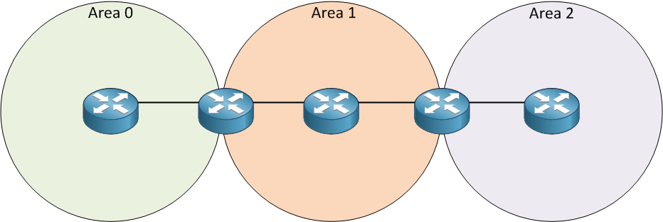
Look at my picture above. We have three areas and on the left side is area 0. Area 2 is behind area 1. Normally this is not going to work since area 2 has to be directly connected to area 0. We can make this work by using a virtual link. By using a virtual link we can extend area 0 through area 1 so area 2 will be “directly connected” to area 0. Let’s take a look at how a virtual link can solve this problem:
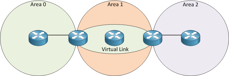
This is basically how a virtual link works. It’s like a tunnel through area 1 to reach area 2. This way area 2 will be directly connected. Now let me show you how to configure a virtual link:
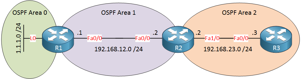
In the example above area 2 is not directly connected to area 0 so we’ll have to use a virtual link between routers R1 and R2, here’s how we do it:
R1(config)#router ospf 1
R1(config-router)#network 1.1.1.0 0.0.0.255 area 0
R1(config-router)#network 192.168.12.0 0.0.0.255 area 1R2(config)#router ospf 1
R2(config-router)#network 192.168.12.0 0.0.0.255 area 1
R2(config-router)#network 192.168.23.0 0.0.0.255 area 2R3(config)#router ospf 1
R3(config-router)#network 192.168.23.0 0.0.0.255 area 2I’ll start with a default OSPF configuration.
R1(config)#router ospf 1
R1(config-router)#area 1 virtual-link 192.168.23.2R2(config)#router ospf 1
R2(config-router)#area 1 virtual-link 1.1.1.1We configure the virtual link between ABRs and we use the area virtual-link command. First, you need to specify the area where we need the virtual link which is area 1 in my example. The second step is to configure the OSPF router ID of the other ABR. Keep this in mind…you need to configure the OSPF router ID and NOT the IP address of the ABR. If everything is OK area 2 will be directly connected to area 0 through our virtual link.
R1# %OSPF-5-ADJCHG Process 1, Nbr 192.168.23.2 on OSPF_VL0 from LOADING to FULL, Loading DoneR2# %OSPF-5-ADJCHG: Process 1, Nbr 1.1.1.1 on OSPF_VL0 from LOADING to FULL, Loading DoneYou will see the message above that tells us the virtual link is established.
R1#show ip ospf virtual-links
Virtual Link OSPF_VL0 to router 192.168.23.2 is up
  Run as demand circuit
  DoNotAge LSA allowed.
  Transit area 1, via interface FastEthernet0/0, Cost of using 1
  Transmit Delay is 1 sec, State POINT_TO_POINT,
  Timer intervals configured, Hello 10, Dead 40, Wait 40, Retransmit 5
    Hello due in 00:00:06
    Adjacency State FULL (Hello suppressed)
    Index 1/2, retransmission queue length 0, number of retransmission 0
    First 0x0(0)/0x0(0) Next 0x0(0)/0x0(0)
    Last retransmission scan length is 0, maximum is 0
Last retransmission scan time is 0 msec, maximum is 0 msecR2#show ip ospf virtual-links
Virtual Link OSPF_VL0 to router 1.1.1.1 is up
Run as demand circuit
DoNotAge LSA allowed.
Transit area 1, via interface FastEthernet0/0, Cost of using 1
Transmit Delay is 1 sec, State POINT_TO_POINT,
Timer intervals configured, Hello 10, Dead 40, Wait 40, Retransmit 5
Hello due in 00:00:05
Adjacency State FULL (Hello suppressed)
Index 1/3, retransmission queue length 0, number of retransmission 0
First 0x0(0)/0x0(0) Next 0x0(0)/0x0(0)
Last retransmission scan length is 0, maximum is 0
Last retransmission scan time is 0 msec, maximum is 0 msecYou can use the show ip ospf virtual-links command to check if your virtual link is working.
R1#show ip ospf database

            OSPF Router with ID (1.1.1.1) (Process ID 1)

		Router Link States (Area 0)

Link ID         ADV Router      Age         Seq#       Checksum Link count
1.1.1.1         1.1.1.1         189         0x80000004 0x00E333 2
192.168.23.2 192.168.23.2 1 (DNA) 0x80000002 0x009816 1R2#show ip ospf database
OSPF Router with ID (192.168.23.2) (Process ID 1)
Router Link States (Area 0)
Link ID ADV Router Age Seq# Checksum Link count
1.1.1.1 1.1.1.1 1 (DNA) 0x80000004 0x00E333 2
192.168.23.2 192.168.23.2 159 0x80000002 0x009816 1If you look at the LSDB you will see that the virtual link shows up as a type 1 router LSA. You can also see DNA which means do not age. For a detailed explanation of the router LSA, take a look at OSPFv2 LSA Type 1 (Router LSA)
Configurations
Want to take a look for yourself? Here you will find the final configuration of each device.
R2
hostname R2
!
interface FastEthernet0/0
 ip address 192.168.12.2 255.255.255.0
!
interface FastEthernet1/0
 ip address 192.168.23.2 255.255.255.0
!
router ospf 1
 area 1 virtual-link 1.1.1.1
 network 192.168.12.0 0.0.0.255 area 1
 network 192.168.23.0 0.0.0.255 area 2
!
end
R1
hostname R1
!
interface Loopback0
 ip address 1.1.1.1 255.255.255.0
!
interface FastEthernet0/0
 ip address 192.168.12.1 255.255.255.0
!
router ospf 1
 area 1 virtual-link 192.168.23.2
 network 1.1.1.0 0.0.0.255 area 0
 network 192.168.12.0 0.0.0.255 area 1
!
end
R3
hostname R3
!
interface FastEthernet0/0
 ip address 192.168.23.3 255.255.255.0
!
router ospf 1
 network 192.168.23.0 0.0.0.255 area 2
!
end
Any other situation where we need a virtual link? What about a discontinuous backbone area? Let me show you an example:
Rene ! this is really grt !
Hi, thank you very much for this very easy to understand explanation. Great job rene.
Glad to hear you like it!
Is it possible to build a virtual link over frame-relay link ? for example in the diagram above if the router in between was a frame-relay switch
Hi Jurati,
Yes this is possible, when your OSPF neighbor adjacency is working over the frame relay link you should be able to configure a virtual link.
Rene