OSPF Loop-Free Alternate (LFA) Fast Reroute (FRR) is a technique where our router is able to pre-install a backup next hop in the routing table and CEF table, making failover very fast (< 50 MS). In some topologies, however, this is not possible. Before you continue with this lesson, make sure you are very familiar with MPLS VPN.
Let’s start with a quick example:
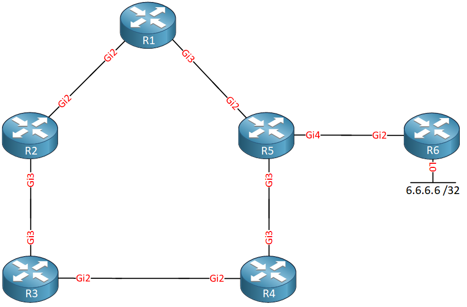
Above we have a bunch of routers. Behind R6 we have a loopback interface with IP address 6.6.6.6/32. We use Gigabit interfaces everywhere with the default cost. Let’s focus on R1.
R1 has two paths to get to 6.6.6.6/32:
- R1 > R5 > R6
- R1 > R2 > R3 > R4 > R5 > R6
The path through R5 is the shortest path, so R5 becomes our next hop. You might think that R2 could be used as a backup path, but that’s not the case. Why? Because R2’s shortest path is through R1:
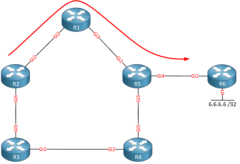
R3 however, is using R4 as its next hop:
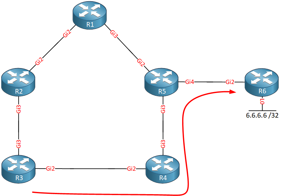
If only there were a way so we could use R3 as a next hop…bypassing R2. Luckily, there is! We can use tunneling to get directly from R1 to R3, bypassing R2:
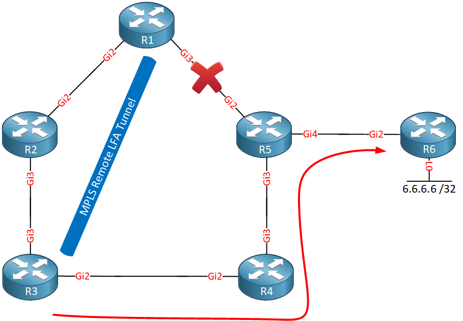
This tunneling method to a remote router to use it as an alternate backup path is called remote LFA (Loop-Free Alternate) FRR (Fast Reroute). A targeted MPLS LDP session between the two routers is used for the tunnel.
Why did R1 select R3?
To understand this, we first have to talk about some remote LFA terminology:
- P space: these are the routers that R1 can reach without using the failed link. This can be calculated by running SPT with R1 as the root. From R1’s perspective, R2 and R3 belong to the P space since it would use its Gigabit 2 interface to reach these two routers.
- Q space: these are the routers that can reach R5 without using the failed link. To figure this out, you have to run SPT with R5 as the root. R5 uses its Gigabit 3 interface to reach R3 and R4, so these two routers belong to the Q space.
- PQ node: this is the router that belongs to both the P and Q space. In our topology, R3 belongs to both the P and Q space, so this router is selected as the PQ node. The PQ node is used as the endpoint for our tunnel.
Now you know why remote LFA is needed and how the remote tunnel endpoint is selected. Let’s look at this in action.
Configuration
Here is the topology we will use:
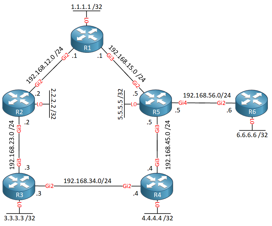
It’s the same topology as before, but I added network and IP addresses. Each router has a loopback interface which is needed because remote LFA uses a targeted LDP session between the two tunnel endpoints. All interfaces are advertised in OSPF area 0.
Configurations
Want to take a look for yourself? Here you will find the startup configuration of each device.
R1
hostname R1
!
interface Loopback0
 ip address 1.1.1.1 255.255.255.255
!
interface GigabitEthernet2
 ip address 192.168.12.1 255.255.255.0
!
interface GigabitEthernet3
 ip address 192.168.15.1 255.255.255.0
!
router ospf 1
 network 1.1.1.1 0.0.0.0 area 0
 network 192.168.12.0 0.0.0.255 area 0
 network 192.168.15.0 0.0.0.255 area 0
!
end
R2
hostname R2
!
interface Loopback0
 ip address 2.2.2.2 255.255.255.255
!
interface GigabitEthernet2
 ip address 192.168.12.2 255.255.255.0
!
interface GigabitEthernet3
 ip address 192.168.23.2 255.255.255.0
!
router ospf 1
 network 2.2.2.2 0.0.0.0 area 0
 network 192.168.12.0 0.0.0.255 area 0
 network 192.168.23.0 0.0.0.255 area 0
!
end
R3
hostname R3
!
interface Loopback0
 ip address 3.3.3.3 255.255.255.255
!
interface GigabitEthernet2
 ip address 192.168.34.3 255.255.255.0
!
interface GigabitEthernet3
 ip address 192.168.23.3 255.255.255.0
!
router ospf 1
 network 3.3.3.3 0.0.0.0 area 0
 network 192.168.23.0 0.0.0.255 area 0
 network 192.168.34.0 0.0.0.255 area 0
!
end
R4
hostname R4
!
interface Loopback0
 ip address 4.4.4.4 255.255.255.255
!
interface GigabitEthernet2
 ip address 192.168.34.4 255.255.255.0
!
interface GigabitEthernet3
 ip address 192.168.45.4 255.255.255.0
!
router ospf 1
 network 4.4.4.4 0.0.0.0 area 0
 network 192.168.34.0 0.0.0.255 area 0
 network 192.168.45.0 0.0.0.255 area 0
!
end
R5
hostname R5
!
interface Loopback0
 ip address 5.5.5.5 255.255.255.255
!
interface GigabitEthernet2
 ip address 192.168.15.5 255.255.255.0
!
interface GigabitEthernet3
 ip address 192.168.45.5 255.255.255.0
!
interface GigabitEthernet4
 ip address 192.168.56.5 255.255.255.0
!
router ospf 1
 network 5.5.5.5 0.0.0.0 area 0
 network 192.168.15.0 0.0.0.255 area 0
 network 192.168.45.0 0.0.0.255 area 0
 network 192.168.56.0 0.0.0.255 area 0
!
end
R6
hostname R6
!
interface Loopback0
 ip address 6.6.6.6 255.255.255.255
!
interface GigabitEthernet2
 ip address 192.168.56.6 255.255.255.0
!
router ospf 1
 network 6.6.6.6 0.0.0.0 area 0
 network 192.168.56.0 0.0.0.255 area 0
!
end
The tunnel uses MPLS LDP, so the first thing we should do is enable MPLS LDP on all interfaces. You can do this with the mpls ip command on each interface or enable MPLS on all interfaces that run OSPF:
R1, R2, R3, R4, R5 & R6
(config-router)#mpls ldp autoconfig area 0
MPLS LDP forms neighbor adjacencies with directly connected neighbors, but in our case, we need an MPLS LDP neighbor adjacency between R1 and R3 who are not directly connected. By default, routers reject targeted MPLS LDP hello requests from non-directly connected routers. This is something we have to enable:


Hi Rene,
Regarding the remote LFA version, when you say “P Space: these are the routers that R1 can reach without using the failed link”, do you mean that, under normal operations, these are the routers that R1 is able to reach without using the link that might fail? Otherwise, why not add R4 to the P Space?
The same question applies for the Q Space.
I’ve posted my question here because I don’t see a dedicated discussion for the remote LFA.
Thanks,
LP
Hello Luis
The official definition according to RFC 4790 is the following:
So for R1, the routers that are reachable without the use of the failed link are R2 and R3 un
... Continue reading in our forumRemote LFA and LFA , these are 2 separate terms ..right ..
can u describe little bit difference between them..??
Hello Narad
In short, an LFA is a next-hop route that delivers a packet to its destination without looping back.
A Loop-Free Alternate (LFA) is a concept that is used in various technologies, including OSPF, other routing protocols, as well as in MPLS. An LFA is a node other than the primary neighbor, or the primary next hop. It is a backup of sorts. Traffic is immediately directed towards the LFA after a network failure. The LFA will receive traffic and will continue to forward it without any knowledge of a failure. LFAs always use a directly connected ne
... Continue reading in our forumHere we did enable LFA FRR because as the article says we do need to enable it for remote LFA FRR.
Question:
What will happen when both LFA and remote LFA options are available.
*I am guessing that normal LFA will be used because remote LFA was introduced only to deal with situations where normal LFA option cannot be used. Kindly elaborate.