Lesson Contents
The non-broadcast network type is designed for non-broadcast multi-access (NBMA) networks where routers can reach each other directly but cannot communicate using multicast, such as Frame Relay or X.25 networks. This means OSPF will perform a DR/BDR election because it is a multi-access network, and since multicast is not possible, we must manually define neighbors. OSPF automatically detects network types based on the underlying media. However, we can manually configure different network types when needed.
Configuration
We are going to configure OSPF with a non-broadcast network type over Ethernet. Here’s what we need to do:
- Change the network type to non-broadcast on all Ethernet interfaces.
- Manually configure OSPF neighbors.
- Advertise networks.
Here’s the topology we’ll use:
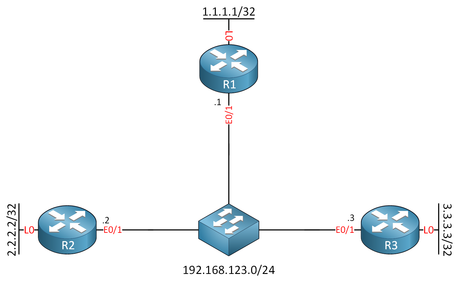
I use an Ethernet switch in the middle because it’s the simplest way to demonstrate this. We don’t have to configure a WAN or tunnels. I’ll show the OSPF packets so you can see that it uses unicast packets. I use Cisco IOS Software [Dublin], Linux Software (X86_64BI_LINUX-ADVENTERPRISEK9-M), Version 17.12.1, RELEASE SOFTWARE (fc5) for this example.
Configurations
Want to take a look for yourself? Here you will find the startup configuration of each device.
R1
hostname R1
!
interface Loopback0
 ip address 1.1.1.1 255.255.255.255
!
interface Ethernet0/1
 ip address 192.168.123.1 255.255.255.0
!
end
R2
hostname R2
!
interface Loopback0
 ip address 2.2.2.2 255.255.255.255
!
interface Ethernet0/1
 ip address 192.168.123.2 255.255.255.0
!
end
R3
hostname R3
!
interface Loopback0
 ip address 3.3.3.3 255.255.255.255
!
interface Ethernet0/1
 ip address 192.168.123.3 255.255.255.0
!
end
We start by changing the network type on all interfaces to non-broadcast:
R1(config)#interface Ethernet0/1
R1(config-if)#ip ospf network non-broadcastR2(config)#interface Ethernet0/1
R2(config-if)#ip ospf network non-broadcastR3(config)#interface Ethernet0/1
R3(config-if)#ip ospf network non-broadcastNext, let’s configure basic OSPF to advertise the loopback interfaces and for the network we configured on the Ethernet0/1 interface:
R1(config)#router ospf 1
R1(config-router)#router-id 1.1.1.1
R1(config-router)#network 192.168.123.0 0.0.0.255 area 0
R1(config-router)#network 1.1.1.1 0.0.0.0 area 0R2(config)#router ospf 1
R2(config-router)#router-id 2.2.2.2
R2(config-router)#network 192.168.123.0 0.0.0.255 area 0
R2(config-router)#network 2.2.2.2 0.0.0.0 area 0R3(config)#router ospf 1
R3(config-router)#router-id 3.3.3.3
R3(config-router)#network 192.168.123.0 0.0.0.255 area 0
R3(config-router)#network 3.3.3.3 0.0.0.0 area 0Since non-broadcast networks don’t support multicast, we must manually configure neighbors. We need to specify each neighbor’s IP address under the OSPF process:
R1(config)#router ospf 1
R1(config-router)#neighbor 192.168.123.2
R1(config-router)#neighbor 192.168.123.3R2(config)#router ospf 1
R2(config-router)#neighbor 192.168.123.1
R2(config-router)#neighbor 192.168.123.3R3(config)#router ospf 1
R3(config-router)#neighbor 192.168.123.1
R3(config-router)#neighbor 192.168.123.2That’s all we need to configure for a non-broadcast network type.
Verification
Let’s verify our configuration. First, let’s check the OSPF network type on R1:
R1#show ip ospf interface Ethernet0/1
Ethernet0/1 is up, line protocol is up
  Internet Address 192.168.123.1/24, Interface ID 3, Area 0
  Attached via Network Statement
  Process ID 1, Router ID 1.1.1.1, Network Type NON_BROADCAST, Cost: 10
  Topology-MTID    Cost    Disabled    Shutdown      Topology Name
        0           10        no          no            Base
  Transmit Delay is 1 sec, State DROTHER, Priority 1
  Designated Router (ID) 3.3.3.3, Interface address 192.168.123.3
  Backup Designated router (ID) 2.2.2.2, Interface address 192.168.123.2
  Timer intervals configured, Hello 30, Dead 120, Wait 120, Retransmit 5
    oob-resync timeout 120
    Hello due in 00:00:19
  Supports Link-local Signaling (LLS)
  Cisco NSF helper support enabled
  IETF NSF helper support enabled
  Can be protected by per-prefix Loop-Free FastReroute
  Can be used for per-prefix Loop-Free FastReroute repair paths
  Not Protected by per-prefix TI-LFA
  Index 1/2/2, flood queue length 0
  Next 0x0(0)/0x0(0)/0x0(0)
  Last flood scan length is 1, maximum is 1
  Last flood scan time is 0 msec, maximum is 0 msec
  Neighbor Count is 2, Adjacent neighbor count is 2
    Adjacent with neighbor 2.2.2.2  (Backup Designated Router)
    Adjacent with neighbor 3.3.3.3  (Designated Router)
  Suppress hello for 0 neighbor(s)
In the output above, we see:
- The network type is non-broadcast.
- The hello interval is 30 seconds, and the dead interval is 120 seconds. This is different from the broadcast network type, which has a hello interval of 10 seconds and a dead interval of 40 seconds.
- Priority of one, which is used in the DR/BDR election.
Let’s verify the network type on R2 and R3 as well:
R2#show ip ospf interface Ethernet0/1 | include Network Type
Process ID 1, Router ID 2.2.2.2, Network Type NON_BROADCAST, Cost: 10R3#show ip ospf interface Ethernet0/1 | include Network Type
Process ID 1, Router ID 3.3.3.3, Network Type NON_BROADCAST, Cost: 10This looks good and all show up as network type non-broadcast. Let’s check our manually configured neighbors:
R1#show ip ospf neighbor

Neighbor ID     Pri   State           Dead Time   Address         Interface
2.2.2.2           1   FULL/BDR        00:01:49    192.168.123.2   Ethernet0/1
3.3.3.3 1 FULL/DR 00:01:57 192.168.123.3 Ethernet0/1R2#show ip ospf neighbor
Neighbor ID Pri State Dead Time Address Interface
1.1.1.1 1 FULL/DROTHER 00:01:33 192.168.123.1 Ethernet0/1
3.3.3.3 1 FULL/DR 00:01:44 192.168.123.3 Ethernet0/1R3#show ip ospf neighbor
Neighbor ID Pri State Dead Time Address Interface
1.1.1.1 1 FULL/DROTHER 00:01:47 192.168.123.1 Ethernet0/1
2.2.2.2 1 FULL/BDR 00:01:51 192.168.123.2 Ethernet0/1We see all neighbor adjacencies. R3 is the DR, and R2 is the BDR.
If you enable a debug, you can see the debugging output shows unicast communication instead of multicast:
R1#debug ip ospf hello
OSPF-1 HELLO Et0/1: Send hello to 192.168.123.2 area 0 from 192.168.123.1
OSPF-1 HELLO Et0/1: Send hello to 192.168.123.3 area 0 from 192.168.123.1?

OSPF-1 HELLO Et0/1: Rcv hello from 2.2.2.2 area 0 192.168.123.2
OSPF-1 HELLO Et0/1: Rcv hello from 3.3.3.3 area 0 192.168.123.3
From this output, you can’t tell that it’s unicast, unless you have seen the hello packet debug for network type broadcast. In that case, it shows that it sends hello packets to the multicast address 224.0.0.5.
Here’s a capture of the hello packet:
Frame 1: 118 bytes on wire (944 bits), 118 bytes captured (944 bits) on interface eth1, id 0
Ethernet II, Src: aa:bb:cc:00:01:10 (aa:bb:cc:00:01:10), Dst: aa:bb:cc:00:02:10 (aa:bb:cc:00:02:10)
Internet Protocol Version 4, Src: 192.168.123.1, Dst: 192.168.123.2
Open Shortest Path First
    OSPF Header
        Version: 2
        Message Type: Hello Packet (1)
        Packet Length: 52
        Source OSPF Router: 1.1.1.1
        Area ID: 0.0.0.0 (Backbone)
        Checksum: 0x68cf [correct]
        Auth Type: Null (0)
        Auth Data (none): 0000000000000000
    OSPF Hello Packet
    OSPF LLS Data Block
Here you can see that this hello packet is destined to the unicast destination IP address 192.168.123.2 (R2). Here you can see all unicast packets between the routers:
Packet Capture: OSPF Network Type Non-Broadcast over Ethernet
Let’s verify full reachability:
I have configured everything correctly why I am still getting
Please help.
Hello speedosuper.
Can you provide us with the topology and configuration?
From my personal experience, it takes a while for the neighborship to form when statically defining neighbors.
David
Hello Speedosuper111
The
ATTEMPT/DROTHERstate with “N/A” Neighbor ID indicates that R1 is sending unicast OSPF Hello packets to the configured neighbors but is not receiving any Hello packets back. This seems to point towards an incomplete non-broadcast configuration.When you set the OSPF network type to non-broadcast (using
... Continue reading in our forumip ospf network non-broadcast), automatic neighbor discovery via multicast is disabled. OSPF must use unicast Hellos instead, which requires manual neighbor configuration on participating routers. It looks like you may have configuredneiThe topology is simply three routers R1, R2 and R3 connected to a switch in a multic-access segment.
R1 has:
R2 has:
... Continue reading in our forumAnyone going to answer??