Lesson Contents
In this lesson, we will configure the OSPF point-to-multipoint non-broadcast network type over a Dynamic Multipoint Virtual Private Network (DMVPN). This network type is similar to point-to-multipoint because it prevents a Designated Router/Backup Designated Router (DR/BDR) election, making it suitable for hub-and-spoke topologies where spokes cannot communicate directly.
The key difference is in the non-broadcast part. The standard point-to-multipoint network type uses multicast OSPF Hellos (224.0.0.5) to discover neighbors automatically. The point-to-multipoint non-broadcast type does not use multicast. Instead, it relies on unicast hello packets, which means we must manually define our OSPF neighbors. This is the perfect solution for Non-Broadcast Multi-Access (NBMA) networks where multicast is unavailable or not configured.
To follow along, you should be familiar with the basics of OSPF. We will use a pre-configured DMVPN topology. This is a hub-and-spoke topology without multicast support, allowing us to focus solely on the OSPF configuration. If you are interested in DMVPN, you can read more about it in our introduction to DMVPN lesson.
Configuration
Here is the topology we’ll use:
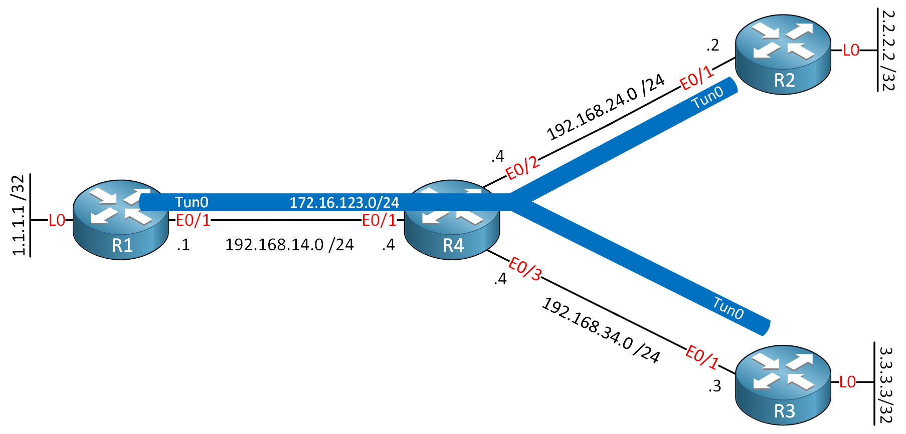
We have a simple hub-and-spoke setup. R1 is the hub, R2 and R3 are the spokes, and R4 acts as the underlying WAN. For this example, I am using Cisco IOS Software [Dublin], Linux Software (X86_64BI_LINUX-ADVENTERPRISEK9-M), Version 17.12.1, RELEASE SOFTWARE (fc5).
Configurations
Want to take a look for yourself? Here you will find the startup configuration of each device.
R1
hostname R1
!
interface Loopback0
 ip address 1.1.1.1 255.255.255.255
!
interface Tunnel0
 ip address 172.16.123.1 255.255.255.0
 no ip redirects
 ip nhrp network-id 1
 tunnel source Ethernet0/1
 tunnel mode gre multipoint
!
interface Ethernet0/1
 ip address 192.168.14.1 255.255.255.0
!
ip route 0.0.0.0 0.0.0.0 192.168.14.4
!
end
R2
hostname R2
!
interface Loopback0
 ip address 2.2.2.2 255.255.255.255
!
interface Tunnel0
 ip address 172.16.123.2 255.255.255.0
 ip nhrp map 172.16.123.1 192.168.14.1
 ip nhrp network-id 1
 ip nhrp nhs 172.16.123.1
 tunnel source Ethernet0/1
 tunnel destination 192.168.14.1
!
interface Ethernet0/1
 ip address 192.168.24.2 255.255.255.0
!
ip route 0.0.0.0 0.0.0.0 192.168.24.4
!
end
R3
hostname R3
!
interface Loopback0
 ip address 3.3.3.3 255.255.255.255
!
interface Tunnel0
 ip address 172.16.123.3 255.255.255.0
 ip nhrp map 172.16.123.1 192.168.14.1
 ip nhrp network-id 1
 ip nhrp nhs 172.16.123.1
 tunnel source Ethernet0/1
 tunnel destination 192.168.14.1
!
interface Ethernet0/1
 ip address 192.168.34.3 255.255.255.0
!
ip route 0.0.0.0 0.0.0.0 192.168.34.4
!
end
R4
hostname R4
!
interface Ethernet0/1
 ip address 192.168.14.4 255.255.255.0
!
interface Ethernet0/2
 ip address 192.168.24.4 255.255.255.0
!
interface Ethernet0/3
 ip address 192.168.34.4 255.255.255.0
!
end
The underlay and tunnel interfaces are already configured and working. This is a standard hub-and-spoke DMVPN Phase 1 setup. The tunnel configuration is the same as the one we used for point-to-multipoint, but without the ip nhrp map multicast command, we are unable to transmit multicast packets. Let’s verify connectivity from the hub to both spokes over the tunnel:
R1#ping 172.16.123.2
Type escape sequence to abort.
Sending 5, 100-byte ICMP Echos to 172.16.123.2, timeout is 2 seconds:
!!!!!
Success rate is 100 percent (5/5), round-trip min/avg/max = 1/1/1 msR1#ping 172.16.123.3
Type escape sequence to abort.
Sending 5, 100-byte ICMP Echos to 172.16.123.3, timeout is 2 seconds:
!!!!!
Success rate is 100 percent (5/5), round-trip min/avg/max = 1/1/1 msConnectivity is good. Now, let’s configure OSPF. We’ll start by setting the correct network type on all tunnel interfaces.
R1(config)#interface Tunnel0
R1(config-if)#ip ospf network point-to-multipoint non-broadcastR2(config)#interface Tunnel0
R2(config-if)#ip ospf network point-to-multipoint non-broadcastR3(config)#interface Tunnel0
R3(config-if)#ip ospf network point-to-multipoint non-broadcastWith the network type set, let’s enable OSPF on our interfaces.
R1(config)#router ospf 1
R1(config-router)#router-id 1.1.1.1
R1(config-router)#network 1.1.1.1 0.0.0.0 area 0
R1(config-router)#network 172.16.123.0 0.0.0.255 area 0R2(config)#router ospf 1
R2(config-router)#router-id 2.2.2.2
R2(config-router)#network 2.2.2.2 0.0.0.0 area 0
R2(config-router)#network 172.16.123.0 0.0.0.255 area 0R3(config)#router ospf 1
R3(config-router)#router-id 3.3.3.3
R3(config-router)#network 3.3.3.3 0.0.0.0 area 0
R3(config-router)#network 172.16.123.0 0.0.0.255 area 0Now let’s wait a moment and check for neighbors.
R1#show ip ospf neighborNothing shows up. This is expected. Remember, this network type doesn’t use multicast for neighbor discovery. We have to tell OSPF where to find its neighbors by configuring them manually.
On the hub (R1), we need to define neighbors for both spokes (R2 and R3). On each spoke, we only need to define a neighbor for the hub:
R1(config)#router ospf 1
R1(config-router)#neighbor 172.16.123.2
R1(config-router)#neighbor 172.16.123.3R2(config)#router ospf 1
R2(config-router)#neighbor 172.16.123.1R3(config)#router ospf 1
R3(config-router)#neighbor 172.16.123.1After defining the neighbors, we should see the adjacencies come up.
R1#
%OSPF-5-ADJCHG: Process 1, Nbr 2.2.2.2 on Tunnel0 from LOADING to FULL, Loading Done
%OSPF-5-ADJCHG: Process 1, Nbr 3.3.3.3 on Tunnel0 from LOADING to FULL, Loading Done
That looks much better. Now our configuration is complete.
Verification
Let’s verify that everything is working as intended. First, we’ll check the OSPF neighbor table.
R1#show ip ospf neighbor

Neighbor ID     Pri   State           Dead Time   Address          Interface
3.3.3.3           0   FULL/  -        00:01:45    172.16.123.3     Tunnel0
2.2.2.2 0 FULL/ - 00:01:41 172.16.123.2 Tunnel0R2#show ip ospf neighbor
Neighbor ID Pri State Dead Time Address Interface
1.1.1.1 0 FULL/ - 00:01:48 172.16.123.1 Tunnel0The hub R1 has established a FULL adjacency with both spokes R2 and R3. Notice there is no DR or BDR, as expected. Here’s a capture of the hello packet:
Frame 11: 138 bytes on wire (1104 bits), 138 bytes captured (1104 bits) on interface eth1, id 0
Ethernet II, Src: aa:bb:cc:00:01:10 (aa:bb:cc:00:01:10), Dst: aa:bb:cc:00:04:10 (aa:bb:cc:00:04:10)
Internet Protocol Version 4, Src: 192.168.14.1, Dst: 192.168.24.2
Generic Routing Encapsulation (IP)
Internet Protocol Version 4, Src: 172.16.123.1, Dst: 172.16.123.2
Open Shortest Path First
    OSPF Header
    OSPF Hello Packet
        Network Mask: 255.255.255.0
        Hello Interval [sec]: 30
        Options: 0x12, (L) LLS Data block, (E) External Routing
        Router Priority: 1
        Router Dead Interval [sec]: 120
        Designated Router: 0.0.0.0
        Backup Designated Router: 0.0.0.0
        Active Neighbor: 2.2.2.2
    OSPF LLS Data Block
Above, you can see that this is a unicast packet. Here’s the entire packet capture file:
Packet Capture: OSPF Network Type P2MP non-broadcast over DMVPN
Let’s check the OSPF interface to confirm the network type and timers.
R1#show ip ospf interface Tunnel0
Tunnel0 is up, line protocol is up
  Internet Address 172.16.123.1/24, Interface ID 9, Area 0
  Attached via Network Statement
  Process ID 1, Router ID 1.1.1.1, Network Type POINT_TO_MULTIPOINT, Cost: 1000
  Topology-MTID    Cost    Disabled    Shutdown      Topology Name
        0           1000      no          no            Base
  Transmit Delay is 1 sec, State POINT_TO_MULTIPOINT
  Timer intervals configured, Hello 30, Dead 120, Wait 120, Retransmit 5
    oob-resync timeout 120
    Hello due in 00:00:21
  Supports Link-local Signaling (LLS)
  Cisco NSF helper support enabled
  IETF NSF helper support enabled
  Can be protected by per-prefix Loop-Free FastReroute
  Can be used for per-prefix Loop-Free FastReroute repair paths
  Not Protected by per-prefix TI-LFA
  Index 1/2/2, flood queue length 0
  Next 0x0(0)/0x0(0)/0x0(0)
  Last flood scan length is 1, maximum is 1
  Last flood scan time is 0 msec, maximum is 0 msec
  Neighbor Count is 2, Adjacent neighbor count is 2
    Adjacent with neighbor 3.3.3.3
    Adjacent with neighbor 2.2.2.2
  Suppress hello for 0 neighbor(s)
We can see that the network type point-to-multipoint is active. This might confuse you, because it doesn’t show “non-broadcast” here. Now, let’s examine the routing table on the hub:
R1#show ip route ospf

      2.0.0.0/32 is subnetted, 1 subnets
O        2.2.2.2 [110/1001] via 172.16.123.2, 00:02:26, Tunnel0
      3.0.0.0/32 is subnetted, 1 subnets
O        3.3.3.3 [110/1001] via 172.16.123.3, 00:02:14, Tunnel0
      172.16.0.0/16 is variably subnetted, 4 subnets, 2 masks
O        172.16.123.2/32 [110/1000] via 172.16.123.2, 00:02:26, Tunnel0
O        172.16.123.3/32 [110/1000] via 172.16.123.3, 00:02:14, Tunnel0
Just like the standard point-to-multipoint type, OSPF automatically installs /32 host routes for each neighbor’s tunnel IP address. This is a key characteristic of both point-to-multipoint network types.
Let’s check the routing table on a spoke router:
R2#show ip route ospf

      1.0.0.0/32 is subnetted, 1 subnets
O        1.1.1.1 [110/1001] via 172.16.123.1, 00:02:49, Tunnel0
      3.0.0.0/32 is subnetted, 1 subnets
O        3.3.3.3 [110/2001] via 172.16.123.1, 00:02:31, Tunnel0
      172.16.0.0/16 is variably subnetted, 4 subnets, 2 masks
O        172.16.123.1/32 [110/1000] via 172.16.123.1, 00:02:49, Tunnel0
O        172.16.123.3/32 [110/2000] via 172.16.123.1, 00:02:31, Tunnel0
Excellent. Spoke R2 has learned about R1 and the other spoke, R3. Notice that R2 learns all routes via R1’s tunnel IP address 172.16.123.1, which is the correct behavior for a hub-and-spoke topology with this network type.
Finally, let’s test end-to-end connectivity by pinging from R2’s loopback to R3’s loopback.
R2#ping 3.3.3.3 source 2.2.2.2
Type escape sequence to abort.
Sending 5, 100-byte ICMP Echos to 3.3.3.3, timeout is 2 seconds:
Packet sent with a source address of 2.2.2.2
!!!!!
Success rate is 100 percent (5/5), round-trip min/avg/max = 1/2/3 ms
The ping is successful. A quick traceroute confirms the path goes through the hub.
R2#traceroute 3.3.3.3 source 2.2.2.2 numeric probe 1
Type escape sequence to abort.
Tracing the route to 3.3.3.3
VRF info: (vrf in name/id, vrf out name/id)
  1 172.16.123.1 1 msec
  2 172.16.123.3 2 msec
The traffic path from R2 to R3 is via R1, as our routing table indicates.