Lesson Contents
In this lesson, we will configure the OSPF point-to-multipoint network type over Dynamic Multipoint Virtual Private Network (DMVPN). This network type tells OSPF not to perform a Designated Router/Backup Designated Router (DR/BDR) election, which is perfect for networks where spokes cannot communicate directly. It allows OSPF to automatically discover neighbors using multicast hello packets, so you don’t have to configure OSPF neighbors manually.
When you run OSPF over a Non-Broadcast Multi-Access (NBMA) network like DMVPN, we need to set the network type to point-to-multipoint manually. The default network (point-to-point) type can cause flapping adjacencies because it’s not designed for a hub connecting to multiple spokes on a single interface. The point-to-multipoint network type solves this.
To follow along, you should be familiar with the basics of OSPF. You don’t need to understand the inner workings of DMVPN because I’ll use a pre-configured topology. If you are interested, you can read more about it in the introduction to DMVPN lesson.
Configuration
Here is the topology:
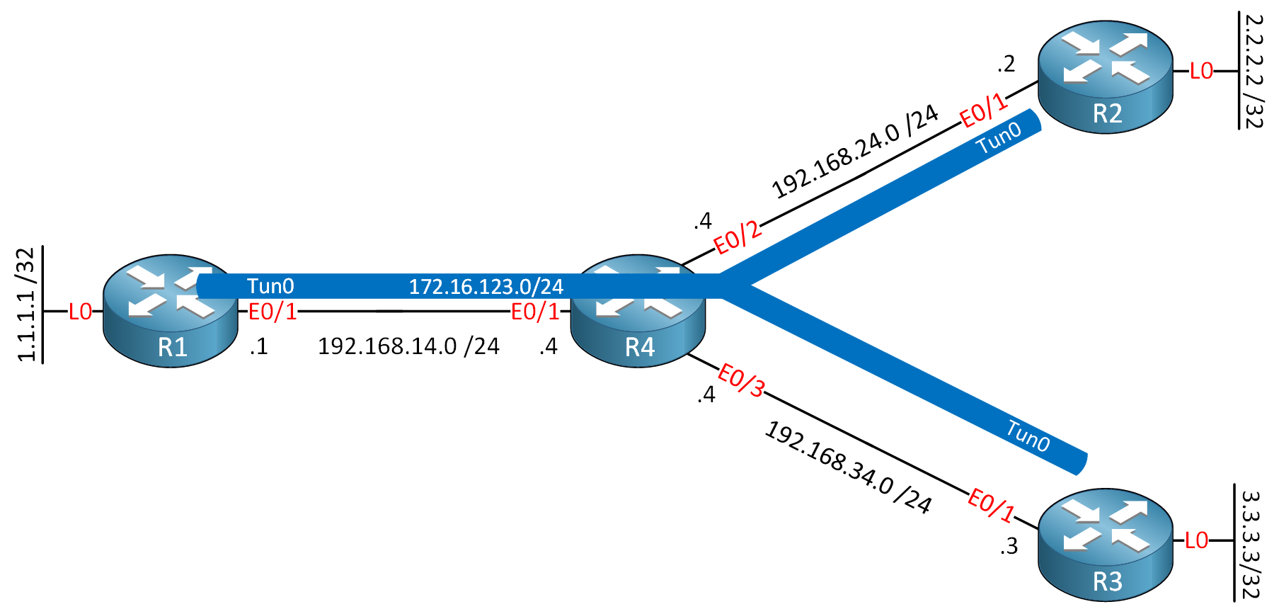
We have four routers. R1 is the hub, and R2 and R3 are spoke routers. R4 sits in the middle to emulate a WAN. I use Cisco IOS Software [Dublin], Linux Software (X86_64BI_LINUX-ADVENTERPRISEK9-M), Version 17.12.1, RELEASE SOFTWARE (fc5) for this example.
Configurations
Want to take a look for yourself? Here you will find the startup configuration of each device.
R1
hostname R1
!
interface Loopback0
 ip address 1.1.1.1 255.255.255.255
!
interface Tunnel0
 ip address 172.16.123.1 255.255.255.0
 no ip redirects
 ip nhrp network-id 1
 tunnel source Ethernet0/1
 tunnel mode gre multipoint
!
interface Ethernet0/1
 ip address 192.168.14.1 255.255.255.0
!
ip route 0.0.0.0 0.0.0.0 192.168.14.4
!
end
R2
hostname R2
!
interface Loopback0
 ip address 2.2.2.2 255.255.255.255
!
interface Tunnel0
 ip address 172.16.123.2 255.255.255.0
 ip nhrp map 172.16.123.1 192.168.14.1
 ip nhrp map multicast 192.168.14.1
 ip nhrp network-id 1
 ip nhrp nhs 172.16.123.1
 tunnel source Ethernet0/1
 tunnel destination 192.168.14.1
!
interface Ethernet0/1
 ip address 192.168.24.2 255.255.255.0
!
ip route 0.0.0.0 0.0.0.0 192.168.24.4
!
end
R3
hostname R3
!
interface Loopback0
 ip address 3.3.3.3 255.255.255.255
!
interface Tunnel0
 ip address 172.16.123.3 255.255.255.0
 ip nhrp map 172.16.123.1 192.168.14.1
 ip nhrp map multicast 192.168.14.1
 ip nhrp network-id 1
 ip nhrp nhs 172.16.123.1
 tunnel source Ethernet0/1
 tunnel destination 192.168.14.1
!
interface Ethernet0/1
 ip address 192.168.34.3 255.255.255.0
!
ip route 0.0.0.0 0.0.0.0 192.168.34.4
!
end
R4
hostname R4
!
interface Ethernet0/1
 ip address 192.168.14.4 255.255.255.0
!
interface Ethernet0/2
 ip address 192.168.24.4 255.255.255.0
!
interface Ethernet0/3
 ip address 192.168.34.4 255.255.255.0
!
end
Don’t worry about the tunnel configuration. It’s pre-configured and works out of the box. This way, you only have to focus on the OSPF configuration. Here’s what you need to know:
- R1 uses Generic Routing Encapsulation (GRE) multipoint, which is a GRE tunnel that can connect to two or more spoke routers using a single interface.
- This is a hub-and-spoke topology, so there is no direct communication between R2 and R3. All traffic goes through R1.
- The tunnel is configured so that multicast traffic is possible.
Let’s get started. Let’s try a ping from R1 to R2 and R3 to make sure the tunnel is up and running:
R1#ping 172.16.123.2
Type escape sequence to abort.
Sending 5, 100-byte ICMP Echos to 172.16.123.2, timeout is 2 seconds:
!!!!!
Success rate is 100 percent (5/5), round-trip min/avg/max = 1/1/1 msR1#ping 172.16.123.3
Type escape sequence to abort.
Sending 5, 100-byte ICMP Echos to 172.16.123.3, timeout is 2 seconds:
!!!!!
Success rate is 100 percent (5/5), round-trip min/avg/max = 1/1/1 msGreat, there is connectivity in the tunnel. Now, let’s configure OSPF. We’ll enable it on the tunnel interfaces and advertise the loopback interfaces:
R1(config)#router ospf 1
R1(config-router)#router-id 1.1.1.1
R1(config-router)#network 1.1.1.1 0.0.0.0 area 0
R1(config-router)#network 172.16.123.0 0.0.0.255 area 0R2(config)#router ospf 1
R2(config-router)#router-id 2.2.2.2
R2(config-router)#network 2.2.2.2 0.0.0.0 area 0
R2(config-router)#network 172.16.123.0 0.0.0.255 area 0R3(config)#router ospf 1
R3(config-router)#router-id 3.3.3.3
R3(config-router)#network 3.3.3.3 0.0.0.0 area 0
R3(config-router)#network 172.16.123.0 0.0.0.255 area 0Let’s check if we have a neighbor adjacency:
R1#show ip ospf neighbor

Neighbor ID     Pri   State           Dead Time   Address         Interface
2.2.2.2           0   EXCHANGE/  -    00:00:39    172.16.123.2    Tunnel0
It’s stuck in the EXCHANGE state. If you look at it a second time, you might see the same output but with a different IP address:
R1#show ip ospf neighbor

Neighbor ID     Pri   State           Dead Time   Address         Interface
3.3.3.3           0   EXCHANGE/  -    00:00:39    172.16.123.3    Tunnel0
On the spoke routers, you might see this:
%OSPF-5-ADJCHG: Process 1, Nbr 1.1.1.1 on Tunnel0 from LOADING to FULL, Loading DoneClearly, something is wrong. Here is the issue:
R1#show ip ospf interface Tunnel0
Tunnel0 is up, line protocol is up
  Internet Address 172.16.123.1/24, Interface ID 9, Area 0
  Attached via Network Statement
  Process ID 1, Router ID 1.1.1.1, Network Type POINT_TO_POINT, Cost: 1000
The default network type for GRE is point-to-point. This won’t work because with point-to-point, we only expect one neighbor on the other side. With our hub-and-spoke topology, R1 has two neighbors (R2 and R3) on the other end. This is one of the reasons why it’s impossible to establish two neighbor adjacencies. Let’s change the network type:
R1(config)#interface Tunnel0
R1(config-if)#ip ospf network point-to-multipoint
As soon as you add this, you should see a neighbor adjacency, but it won’t last. Here’s why:
R1#show ip ospf interface Tunnel0
Tunnel0 is up, line protocol is up
  Internet Address 172.16.123.1/24, Interface ID 9, Area 0
  Attached via Network Statement
  Process ID 1, Router ID 1.1.1.1, Network Type POINT_TO_MULTIPOINT, Cost: 1000
  Topology-MTID    Cost    Disabled    Shutdown      Topology Name
        0           1000      no          no            Base
  Transmit Delay is 1 sec, State POINT_TO_MULTIPOINT
  Timer intervals configured, Hello 30, Dead 120, Wait 120, Retransmit 5
The network type is configured correctly, but take a closer look at the timers. Now let’s check one of the spoke routers:
R2#show ip ospf interface Tunnel0
Tunnel0 is up, line protocol is up
  Internet Address 172.16.123.2/24, Interface ID 9, Area 0
  Attached via Network Statement
  Process ID 1, Router ID 2.2.2.2, Network Type POINT_TO_POINT, Cost: 1000
  Topology-MTID    Cost    Disabled    Shutdown      Topology Name
        0           1000      no          no            Base
  Transmit Delay is 1 sec, State POINT_TO_POINT
  Timer intervals configured, Hello 10, Dead 40, Wait 40, Retransmit 5
R2 and R3 are configured with the default network type, which is point-to-point. The issue we have is that it uses different timers. You could make this work by changing the timers, but it’s best to use the same network type on R2 and R3 as well:
R2 & R3
(config)#interface Tunnel0
(config-if)#ip ospf network point-to-multipoint
That’s all we have to configure.
Verification
Let’s verify our work. First, let’s check the neighbor adjacencies:
R1#show ip ospf neighbor

Neighbor ID     Pri   State           Dead Time   Address         Interface
3.3.3.3           0   FULL/  -        00:01:45    172.16.123.3    Tunnel0
2.2.2.2 0 FULL/ - 00:01:36 172.16.123.2 Tunnel0R2#show ip ospf neighbor
Neighbor ID Pri State Dead Time Address Interface
1.1.1.1 0 FULL/ - 00:01:55 172.16.123.1 Tunnel0R3#show ip ospf neighbor
Neighbor ID Pri State Dead Time Address Interface
1.1.1.1 0 FULL/ - 00:01:44 172.16.123.1 Tunnel0We have all neighbor adjacencies required, the state is FULL and there is no DR/BDR election. With a packet capture, you can see the first hello packet uses multicast destination 224.0.0.5:
Frame 10: 134 bytes on wire (1072 bits), 134 bytes captured (1072 bits) on interface eth1, id 0
Ethernet II, Src: aa:bb:cc:00:01:10 (aa:bb:cc:00:01:10), Dst: aa:bb:cc:00:04:10 (aa:bb:cc:00:04:10)
Internet Protocol Version 4, Src: 192.168.14.1, Dst: 192.168.24.2
Generic Routing Encapsulation (IP)
Internet Protocol Version 4, Src: 172.16.123.1, Dst: 224.0.0.5
Open Shortest Path First
    OSPF Header
    OSPF Hello Packet
        Network Mask: 255.255.255.0
        Hello Interval [sec]: 30
        Options: 0x12, (L) LLS Data block, (E) External Routing
        Router Priority: 1
        Router Dead Interval [sec]: 120
        Designated Router: 0.0.0.0
        Backup Designated Router: 0.0.0.0
    OSPF LLS Data Block
Here is the entire packet capture:
Packet Capture: OSPF Network Type P2MP over DMVPN
Let’s check the network type:
R1#show ip ospf interface tunnel0 | include Network Type
Process ID 1, Router ID 1.1.1.1, Network Type POINT_TO_MULTIPOINT, Cost: 1000R2#show ip ospf interface tunnel0 | include Network Type
Process ID 1, Router ID 2.2.2.2, Network Type POINT_TO_MULTIPOINT, Cost: 1000R3#show ip ospf interface tunnel0 | include Network Type
Process ID 1, Router ID 3.3.3.3, Network Type POINT_TO_MULTIPOINT, Cost: 1000The network type is set to point-to-multipoint on all tunnel interfaces. Let’s check some routes:
R1#show ip route ospf

      2.0.0.0/32 is subnetted, 1 subnets
O        2.2.2.2 [110/1001] via 172.16.123.2, 00:03:59, Tunnel0
      3.0.0.0/32 is subnetted, 1 subnets
O        3.3.3.3 [110/1001] via 172.16.123.3, 00:03:51, Tunnel0
      172.16.0.0/16 is variably subnetted, 4 subnets, 2 masks
O        172.16.123.2/32 [110/1000] via 172.16.123.2, 00:03:59, Tunnel0
O        172.16.123.3/32 [110/1000] via 172.16.123.3, 00:03:51, Tunnel0
Notice that OSPF automatically creates /32 host routes for each neighbor’s tunnel IP address. This is a characteristic of point-to-multipoint networks. Let’s check one of the spoke routers:
R2#show ip route ospf

      1.0.0.0/32 is subnetted, 1 subnets
O        1.1.1.1 [110/1001] via 172.16.123.1, 00:04:48, Tunnel0
      3.0.0.0/32 is subnetted, 1 subnets
O        3.3.3.3 [110/2001] via 172.16.123.1, 00:04:36, Tunnel0
      172.16.0.0/16 is variably subnetted, 4 subnets, 2 masks
O        172.16.123.1/32 [110/1000] via 172.16.123.1, 00:04:48, Tunnel0
O        172.16.123.3/32 [110/2000] via 172.16.123.1, 00:04:36, Tunnel0
Excellent. We see all the required routes. Note that the next hop IP address of all these routes is the IP address of R1’s tunnel interface.
Let’s try a ping from the loopback of R2 to the loopback of R3:
R2#ping 3.3.3.3 source 2.2.2.2
Type escape sequence to abort.
Sending 5, 100-byte ICMP Echos to 3.3.3.3, timeout is 2 seconds:
Packet sent with a source address of 2.2.2.2
!!!!!
Success rate is 100 percent (5/5), round-trip min/avg/max = 1/1/1 ms
This is working! Let’s try a traceroute as well:
R2#traceroute 3.3.3.3 source 2.2.2.2 numeric probe 1
Type escape sequence to abort.
Tracing the route to 3.3.3.3
VRF info: (vrf in name/id, vrf out name/id)
  1 172.16.123.1 1 msec
  2 172.16.123.3 1 msec
This proves that our traffic goes from R2 to R1 to R3.