Lesson Contents
InterVLAN routing means routing packets between VLAN. When we want to send packets from one VLAN to another, we need routing. Without routing, VLANs are isolated networks that can’t communicate with each other. Routers or multilayer switches (Layer three switches) both allow us to route packets between VLANs, and there are three ways of doing so:
- Router on a stick (ROAS)
- Switch Virtual Interface (SVI)
- Routed ports
In this lesson, I’ll explain the different options and I’ll show you how to configure interVLAN routing.
Key Takeaways
- Router on a Stick uses a single router interface with sub-interfaces and 802.1Q trunking—ideal for small networks but creates a single point of failure
- SVI (Switch Virtual Interface) creates virtual layer 3 interfaces on multilayer switches for each VLAN—best for multiple devices in the same VLAN
- Routed Ports convert switch ports to layer 3 interfaces—perfect for point-to-point connections with only one device per VLAN
- All three methods support dynamic routing protocols like EIGRP and OSPF
- Multilayer switches require the
ip routingcommand to build a routing table
Prerequisites
Before starting this lesson, you should have a basic understanding of:
- VLAN basics: How to create and assign VLANs on switches
- Trunking: 802.1Q trunk configuration and operation
- IP addressing: Subnetting and default gateways
- Basic routing: How routers forward packets between networks
Having said that, let’s get started.
Router on a Stick
With a router on a stick, we use an external router connected to a switch via 802.1Q encapsulation to create a trunk. Traffic from one VLAN will go over the 802.1Q trunk to the router, which routes it, then sends it back down the 802.1Q trunk on the other VLAN. Because we use a single physical interface with two or more VLANs, it’s as if the router is “on a stick”. Here is an example:
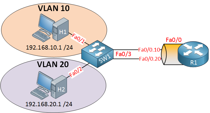
SW1 has two VLANs, so we have two different subnets. If we want communication between these VLANs, we’ll need a device that can route traffic. In this example, we’ll use a router for the job. R1 will need access to both VLANs, so we’ll create an 802.1Q trunk between SW1 and R1. Here’s how to configure this:
SW1(config)#interface fa0/3
SW1(config-if)#switchport trunk encapsulation dot1q
SW1(config-if)#switchport mode trunk
SW1(config-if)#switchport trunk allowed vlan 10,20
This is how we configure SW1. Make interface fa0/3 a trunk port, and for security measures, I made sure that only VLAN 10 and 20 are allowed. Let’s create two sub-interfaces and assign the correct VLANs:
R1(config)#interface fa0/0.10
R1(config-subif)#encapsulation dot1Q 10
R1(config-subif)#ip address 192.168.10.254 255.255.255.0
R1(config)#interface fa0/0.20
R1(config-subif)#encapsulation dot1Q 20
R1(config-subif)#ip address 192.168.20.254 255.255.255.0
Don’t forget to add an IP address for each VLAN. Here’s what the routing table looks like:
R1#show ip route

Codes: C - connected, S - static, R - RIP, M - mobile, B - BGP
       D - EIGRP, EX - EIGRP external, O - OSPF, IA - OSPF inter area
       N1 - OSPF NSSA external type 1, N2 - OSPF NSSA external type 2
       E1 - OSPF external type 1, E2 - OSPF external type 2
       i - IS-IS, su - IS-IS summary, L1 - IS-IS level-1, L2 - IS-IS level-2
       ia - IS-IS inter area, * - candidate default, U - per-user static route
       o - ODR, P - periodic downloaded static route

Gateway of last resort is not set

C    192.168.10.0/24 is directly connected, FastEthernet0/0.10
C    192.168.20.0/24 is directly connected, FastEthernet0/0.20
The router can route because these two networks are directly connected. On my hosts, I configured an IP address and default gateway:
C:\Documents and Settings\H1>ipconfig

Windows IP Configuration

Ethernet adapter Local Area Connection:

        Connection-specific DNS Suffix  . :
        IP Address. . . . . . . . . . . . : 192.168.10.1
        Subnet Mask . . . . . . . . . . . : 255.255.255.0
        Default Gateway . . . . . . . . . : 192.168.10.254
C:\Documents and Settings\H2>ipconfig
Windows IP Configuration
Ethernet adapter Local Area Connection:
Connection-specific DNS Suffix . :
IP Address. . . . . . . . . . . . : 192.168.20.1
Subnet Mask . . . . . . . . . . . : 255.255.255.0
Default Gateway . . . . . . . . . : 192.168.20.254Let’s try a ping:
C:\Documents and Settings\H1>ping 192.168.20.1

Pinging 192.168.20.1 with 32 bytes of data:

Reply from 192.168.20.1: bytes=32 time<1ms TTL=128
Reply from 192.168.20.1: bytes=32 time<1ms TTL=128
Reply from 192.168.20.1: bytes=32 time<1ms TTL=128
Reply from 192.168.20.1: bytes=32 time<1ms TTL=128

Ping statistics for 192.168.1.2:
    Packets: Sent = 4, Received = 4, Lost = 0 (0% loss),
Approximate round trip times in milli-seconds:
    Minimum = 0ms, Maximum = 0ms, Average = 0ms
That’s how you do it. So why would you want to use a solution like this? It’s cheap! You don’t need a multilayer switch for your routing. Any layer two switch will do.
Some of the disadvantages of this solution are that your router is a single point of failure and that traffic flows up and down on the same link, which might cause congestion.
Configurations
Want to take a look for yourself? Here, you will find the final configuration of each device.
R1
hostname R1
!
interface fastEthernet0/0.10
 encapsulation dot1Q 10
 ip address 192.168.10.254 255.255.255.0
!
interface fastEthernet0/0.20
 encapsulation dot1Q 20
 ip address 192.168.20.254 255.255.255.0
!
end
SW1
hostname SW1
!
interface fastEthernet0/1
 switchport mode access
 switchport access vlan 10
!
interface fastEthernet0/2
 switchport mode access
 switchport access vlan 20
!
interface fastEthernet0/3
 switchport trunk encapsulation dot1q
 switchport mode trunk
 switchport trunk allowed vlan 10,20
end
So, what other solutions do we have?
SVI (Switch Virtual Interface)
With an SVI, we use a multilayer switch (Layer three switch). This means the switch can also route traffic. Here is an example:
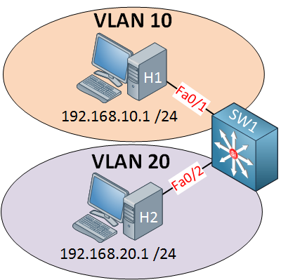
This is the picture of a multilayer switch. I can configure something called an SVI (Switch Virtual Interface) for each VLAN and put an IP address on it. This IP address can be used for computers as their default gateway. Here’s how to configure it:
SW1(config)#ip routing
SW1(config)#interface vlan 10
SW1(config-if)#no shutdown
SW1(config-if)#ip address 192.168.10.254 255.255.255.0
SW1(config)#interface vlan 20
SW1(config-if)#no shutdown
SW1(config-if)#ip address 192.168.20.254 255.255.255.0
Start by enabling routing using the ip routing command. If you forget this, your switch won’t build a routing table! The next step is to create an SVI for VLAN 10 and 20 and configure IP addresses on them. This configuration might look familiar if you worked with layer two switches before. On a layer two switch like the Cisco Catalyst 2950/2960, we also have an SVI, but you can only use it for remote management.
Once you create an SVI and type no shutdown it will normally be “up” since it’s only a virtual interface, there are however, a number of requirements, or it will show up as “down”:
- The VLAN has to exist in the VLAN database, and it should be active.
- At least one access or trunk port should use this VLAN actively, and it should be in spanning tree forwarding mode.
Simply said: the VLAN has to be active somehow, or your SVI will go down.
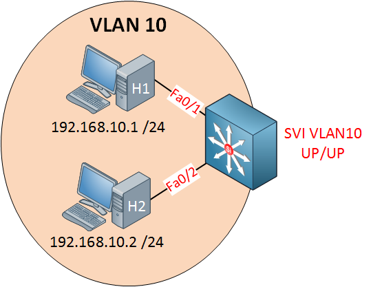
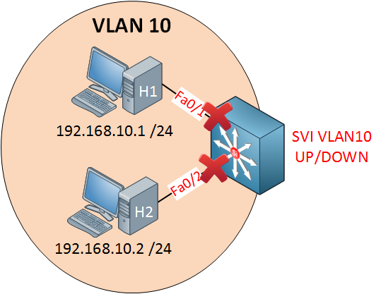
I have two computers in VLAN 10 and created an SVI for VLAN 10.
SW1#show ip interface brief vlan 10
Interface              IP-Address      OK? Method Status                Protocol
Vlan10                 192.168.10.254  YES manual up         up
You’ll see that the status says up/up, so that’s good.
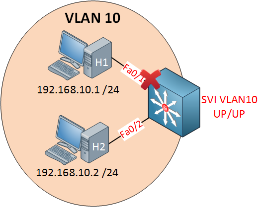
If I shut down one interface, nothing will change, my SVI will still show up/up because interface fa0/2 is still active.
SW1#show ip interface brief vlan 10
Interface              IP-Address      OK? Method Status                Protocol
Vlan10                 192.168.10.254  YES manual up         down
Once I shut both interfaces, we don’t have anything active anymore in VLAN 10. As a result, the SVI will go to up/down.
Now, if I want, I can exclude an interface from the SVI state. Imagine I want to make sure that whatever happens to interface fa0/2 doesn’t influence the SVI state:
SW1(config)#interface fa0/2
SW1(config-if)#switchport autostate exclude
I can use the switchport autostate exclude command. This means it won’t influence the state of the SVI interface anymore. Fa0/1 is the only interface that can now influence the SVI state. As soon as it goes down, you’ll see that the SVI state also goes down, even though fa0/2 is still up and running.
Enough about the SVI. There’s another method we can use on our multilayer switch for routing. By default, all interfaces on a switch are switch ports (layer two), but we can change them to routed ports (layer three). A routed port is the exact same interface as what we use on a router.
Configurations
Want to take a look for yourself? Here, you will find the final configuration of SW1.
SW1
hostname SW1
!
ip routing
!
interface vlan 10
ip address 192.168.10.254 255.255.255.0
!
interface vlan 20
ip address 192.168.20.254 255.255.255.0
!
interface FastEthernet0/2
switchport autostate exclude
!
end
Enough about SVI, there’s another method we can use for routing on multilayer switches.


Rene,
I have a Cisco SG300-28 PoE+ switch and am having an old age moment in setting up VLans. Would you know the answer to or be able to assist with the following:
My network has:
1 router, which also handles DHCP duties with one range currently specified 192.168.1.x/24
1 switch
1 WAP
and about 40 nodes
I want to create multiple VLANS on the Cisco SG300 switch.
Vlan10 - Mgmnt
Vlan20 - Children
Vlan30 - AV
Vlan40 - Automation
Vlan50 - VoIP
Vlan60 - Guest
What are the steps necessary after creating the Vlans in this scenario to make things work?
WAP is on port 1
... Continue reading in our forumHi JT,
I did a write-up once for the SG300, it might help:
https://networklessons.com/switching/cisco-small-business-switch-vlan-configuration
If you run the SG300 in L3 mode then it can route between the VLANs and you can use it as a DHCP server. There are a couple of things you have to do if you want your hosts in the different VLANs to use the router for Internet access.
First you’ll need another subnet between the SG300/router so that they can reach each other.
Once you can ping between the SG300/router, you’ll need three more things:
- The SG300 requires a
... Continue reading in our forumQuestion in regard SVI’s:
If I have 50 SVI’s configured then all the SVI’s can communicate with one another then How would you secure communication between them?
Please advise
Hi Alfredo,
You can attach access-lists to the SVI interfaces, this will prevent devices behind one SVI to communicate with devices in another SVI.
Just follow this example but attach it to the SVI interface:
https://networklessons.com/security/extended-access-list-example-on-cisco-router
Rene
I studied my CCNP SWITCH but going through your training I came to realize that I have gaps of information that I never saw on my training.
Thanks and keep the good work.