Lesson Contents
In networking, there are a number of different topologies that you will encounter. In this lesson, I’ll explain the most common topologies that are covered in the CCNA Routing & Switching exam(s).
Let’s start with the star topology…
Star Topology
You will see the star topology often when we talk about switches, here’s an example:
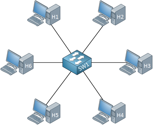
It’s called a star topology because all communication has to go through the switch, it is the central component of our network.
Full Mesh
The full mesh topology means that each device is connected to all other devices. Here’s an example:
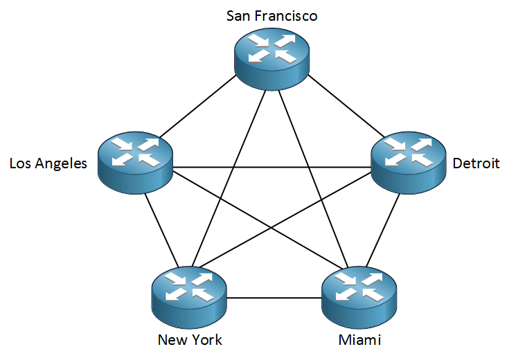
The advantage of a full mesh topology is that you have full redundancy. For example, in the picture above we can see routers in different cities. We can go from Los Angeles to New York with a direct connection. If this link fails, there are still plenty of backup links we can choose from. The downside of a full mesh topology is that it’s expensive. For each link, you will need to pay for the connection and you require additional interfaces on your routers.
Partial Mesh
An alternative to full mesh is the partial mesh topology. This is a trade-off between cost and redundancy. Here’s an example:
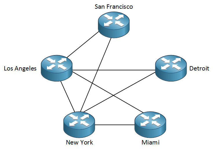
The Los Angeles and New York sites are the most important ones, so they are connected to all other sites. There is no direct connection between San Francisco, Detroit and Miami. This doesn’t mean that these sites won’t be able to communicate with each other but communication has to go through the Los Angeles or New York sites.
You might also encounter partial mesh topologies on our LANs. For example:
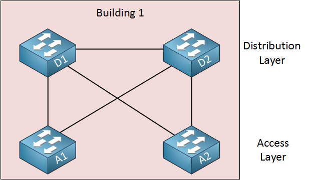
Above we see the switches in a single building. The access layer switches (A1 and A2) are connected to the distribution layer switches (D1 and D2) with partial mesh. There is no link in between the two access switches. The distribution layer switches however are connected to each other and the two access layer switches (full mesh).
Hub and Spoke
Another topology we might encounter is the hub and spoke topology:
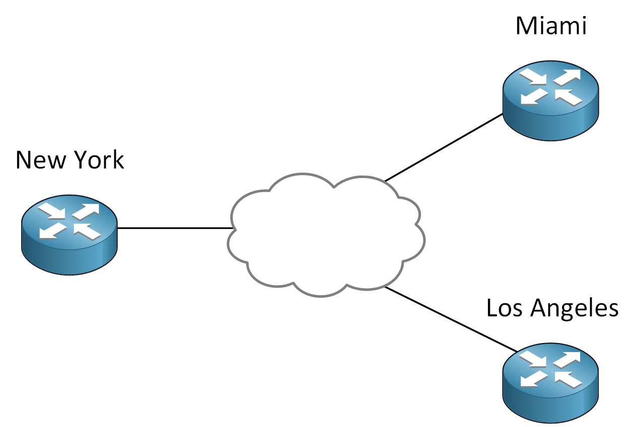
In this topology, we have one central device called the hub, and the other devices are called spokes. Above we have three routers. The headquarters of this company is in New York. This is where all company resources are located. There are also branch offices that need to access the headquarters resources. In this case, it makes sense to build a hub and spoke topology where the New York router becomes the hub and the Miami and Los Angeles routers are spoke routers. Traffic between spoke routers is often routed through the hub router because of security reasons. The spoke routers could be simple routers while the headquarters has a powerful firewall that inspects all traffic.
Hi guys.
I was not able to find lessons about that.
Can you explain the difference between a LAN SWITCH and a SAN SWITCH?
Thank you very much
Hello Giovanni
The first thing we should do is determine the difference between a LAN and a SAN. A LAN is already well defined within the Introduction to LANs lesson. A SAN is a storage area network, which is a network architecture that is used to provide access to consolidated data storage. This is often used within a datacenter to provide servers with direct high-speed access to a shared storage repository.
SANs can use conventional Layer 2 networking protocols such as Ethernet, but must often use a specialized Layer 3 protocol called Fiber Channel (FC) wh
... Continue reading in our forumHello Pau
Yes, you are correct. I believe that the point of the diagram was to show the various interconnections that can be made without actually showing every individual link. However, I will let Rene know to clarify and possibly to modify the image.
Thanks again for pointing this out!
Laz
HI Laz,
Wouldn`t be a good idea interconnect core 1 with core 2?
Also we have the option of one more link redundancy between cores and NY, but I guess it`s much more expensive ports in NY router than ports of core switches.
Let me know your opinion about this design
Thanks.
Victor Hugo
Hello Victor
Yes, your suggestion is excellent. This would allow traffic between buildings to avoid going through the New York router, offloading a lot of work from that device. It would also provide a level of redundancy, in case one of the core routers failed (if you enable something like load-balanced routing, HSRP, Stacking, or VSS.
You are correct again, that it would be beneficial to enable redundancy at the New York router, for both links, as well as in hardware. The NY router is a single point of failure that would cause a disconnection between multi
... Continue reading in our forum