Lesson Contents
Ethernet is not a single protocol but an entire collection of different standards. These standards come from the IEEE and all of them start with 802.3 in their name. Ethernet is also pretty old, the first memo about Ethernet was written by Bob Metcalfe back in 1973.
Despite its age, Ethernet is the dominant choice for LANs. There are many different standards with speeds of 10 Mbps (megabits per second) up to 100 Gbps (gigabits per second). Here’s an overview with some popular Ethernet standards:
| Bandwidth | Common Name | Informal name | IEEE name | Cable Type |
| 10 Mbps | Ethernet | 10BASE-T | 802.3 | UTP 100m |
| 100 Mbps | Fast Ethernet | 100BASE-T | 802.3u | UTP 100m |
| 1000 Mbps | Gigabit Ethernet | 1000BASE-LX | 802.3z | Fiber 5000m |
| 1000 Mbps | Gigabit Ethernet | 1000BASE-T | 802.3ab | UTP 100m |
| 10 Gbps | 10 Gigabit Ethernet | 10GBASE-T | 802.3an | UTP 100m |
On the physical layer, there are different cable options and different speeds. One of the advantages of Ethernet, however, is that it uses the same data link layer standard. You can mix different Ethernet standards in your network. Here’s an example:
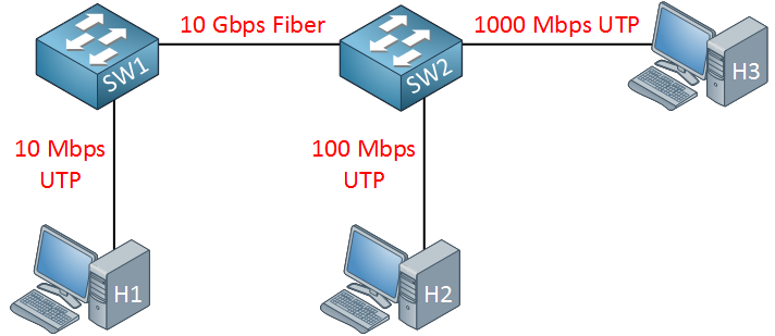
Above we see three hosts that are connected to two switches using different Ethernet standards. The connection between the switches is a 10 Gbps fiber connection. This network will be able to forward Ethernet frames even though we mix different standards.
Ethernet describes the physical and data link layer. Let’s take a closer look at both…
Physical Layer
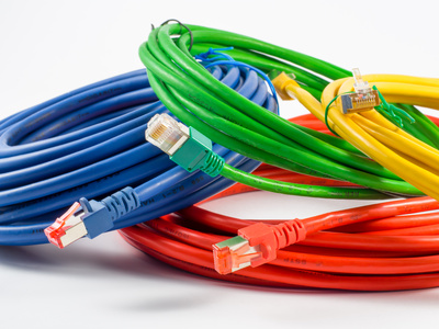
There are two cables we can use for Ethernet:
- UTP (Unshielded Twisted Pair)
- Glass fiber
UTP Cabling
UTP cables use copper to transmit an eletrical signal. The advantage of UTP is that it’s cheap and easy to work with. One of the disadvantages is that you can only use it up to 100 meter.
To use an electrical signal to transmit data, we need two things:
- An electrical circuit.
- Something to communicate a 1 or 0 to the other side.
To create the electrical circuit, we use two wires inside the UTP cable to create a loop, which allows electricity to flow:
To send data between two devices, we need an encoding scheme. For example, when we want to send a 1 we send a high voltage. When we want to send a 0, we send a low voltage. When both devices use the same encoding scheme, we can exchange data.
One issue with electricity when sending it through a wire is that we get EMI (electromagnetic interference). Twisting the cables helps to cancel most of the EMI between the wire pairs. This is also known as crosstalk.
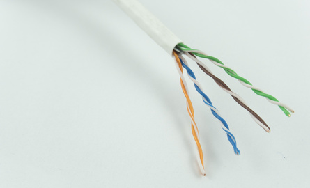
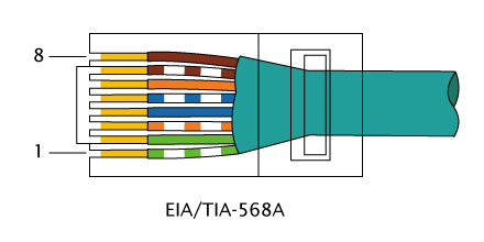
As you can see above, the UTP cable has 4 wire pairs with 2 wires each. Each wire pair has two matching colors. For example, blue and blue-white. On the end of the UTP cable, we use an RJ45 connector:
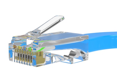
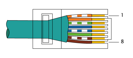
The RJ45 connector has 8 spots where the wires can be inserted, called “pins”. We count the pin numbers from left to right, looking at the bottom of the RJ45 connector:
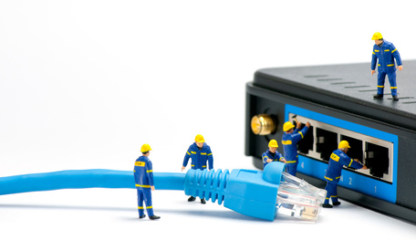
The cable with connectors is then connected to a NIC (Network Card) or a switch port:
The order of the wires in the RJ45 connector is important. There are two options.
Straight Through Cable
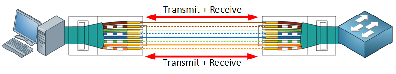
10BASE-T and 100BASE-T both use only two wire pairs in a UTP cable, one for transmission and the other for receiving. Here is an example of a computer that is connected to a switch:
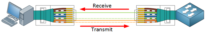
On the left side, we use the orange/orange-white wires to transmit data (pin 1 and 2), the green/green-white wires (pin 3 and 6) are used to receive data. On the other end, we receive data on the orange/orange-white wires (pin 1 and 2) and transmit on the green/green-white wires (pin 3 and 6).
We call this the straight through cable, the wires on both ends are connected one-to-one.
Crossover Cable
What if we want to connect two switches to each other? If both of them transmit on pins 3 and 6, we get a collision on the wire.
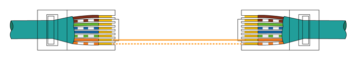
To make sure we send/receive on the correct pins, we use a different type of cable called a crossover cable. The UTP cable is still the same but on one end of the cable, we have the wires in a different order in the RJ45 connector like this:
Here’s an example of two switches with a crossover cable in between:
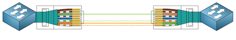
The pins in the RJ45 connector are now crossed like this:
| Left Switch | Right Switch |
| pin 1 | pin 3 |
| pin 2 | pin 6 |
| pin 3 | pin 1 |
| pin 6 | pin 2 |
Cable Selection
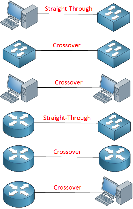
When do we use a straight through or crossover cable? Something to keep in mind is that computers, printers, routers, access points and such use pin 1 and 2 to transmit their data. Switches use pin 3 and 6 to transmit data.
Here’s an overview with different devices and the cable type you should use:
1000BASE-T (Gigabit Cabling)
In the examples above we had two wire pairs, one for transmission and the other one for receiving. Gigabit Ethernet, however, uses all 4 wire pairs. Instead of using different wire pairs for transmission / receiving, it is able to transmit and receive simultaneously on each wire pair.
The pin layout in the RJ45 connector is the same but we use additional wires:
The crossover cable is the same but in addition, it also crosses:
- Pin 4 to 7
- Pin 5 to 8
- Pin 7 to 4
- Pin 8 to 5
It’s very unlikely that you ever need a Gigabit crossover cable because of the auto-mdix feature.
Fiber Cabling
An alternative to UTP is fiber cabling.
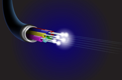
Instead of an electrical signal, we transmit light from one end to another through glass or plastic. One of the advantages is that there is less signal loss over long distances. With a UTP cable, the maximum distance is 100 meters. Fiber cables allow you distances up to many kilometers / miles. You also don’t have any issues with EMI.
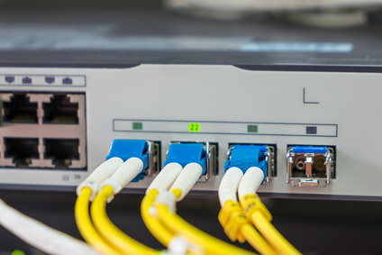
Most switches have a lot of regular ports for UTP cables and a few (hot) swappable slots. In these slots, you can insert an SFP so you can decide if you want another UTP port or a fiber port.
Duplex
To understand duplex, we have to take a history lesson. Back in 1990, we didn’t have switches but only something called a hub. On the outside, a hub looks the same as a switch. It has a couple of RJ45 ports that we can use to connect computers.
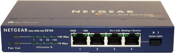
A hub, however, is a dumb device. When it receives an electrical signal on one port, it repeats this signal on all other ports…even when it receives multiple signals at the same time. This could cause collisions on the network, here’s an example to illustrate this:
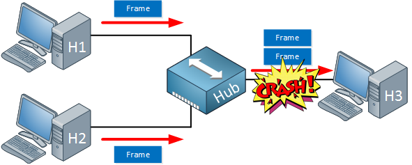
Above we see that H1 and H2 are both sending an Ethernet frame. The hub repeats these frames on the port that connects to H3. When this happens at the same time, we get a collision and both frames are lost.
To get around this, we have to use half duplex.
Half duplex means that we can’t send and receive at the same time. When one computer is transmitting, everyone else has to wait. When nobody is transmitting, we can take a shot and transmit a frame.
This doesn’t mean however that we are completely free of collisions. When two computers decide the “line is free” and start transmitting, we still get a collision. To solve this issue, we have a protocol called CSMA/CD:
- CS = Carrier Sense
- MA = Multi Access
- CD = Collision Detection
Carrier sense means we can “listen” on the cable to hear if anything is going on, in other words, if another computer is sending data at this moment. Multi-access means everyone can access our physical medium but it has to be clear…no other computer should be sending at that moment.
In case two computers send at the same time we have a collision, since we can detect this (its carrier sense right) CSMA/CD will solve this as following:
- The two computers that had the collision will start jamming the physical medium; this will ensure nobody else can transmit at that moment.
- The two computers each start a random clock.
- When the time of the random clock elapses they retransmit.
Since the clock is random, both computers will have a different timer and one of them will send its data before the other. By jamming the physical medium we will be certain that no other computer will get a chance to send data before them.
Nowadays it’s hard to find a hub, they were all replaced by switches. When the first switches were announced, they were much pricier than hubs.
Switches are intelligent devices. They can read the Ethernet frame and forward it only to the device that needs it. When it has two forward two frames on a port, it can queue the second one, preventing collisions.
Switches operate in full duplex which means everyone can send and transmit at the same time. Because we don’t have any collisions, we don’t need the CSMA/CD protocol anymore and it is disabled by default on a switch.
Data Link Layer
One of the great things about Ethernet is that although we have different standards, they all use a common Ethernet frame. This frame hasn’t changed much since the original Ethernet standards from the 70s. Here’s what an Ethernet frame looks like:
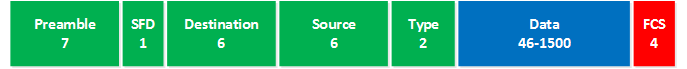
Let me explain the different fields:
- Preamble: this is a 7-byte pattern of ones and zeroes and is used for synchronization.
- SFD: the “start frame delimiter” marks the end of the preamble and tells the receiver that the next fields will be the actual Ethernet frame, starting with the destination field.
- Destination: this is the destination MAC address of the receiver.
- Source: the source MAC address of the device that sent the frame.
- Type: this tells us what is carried inside the Ethernet frame. An IPv4 packet, IPv6 packet or something else.
- Data: this carries the actual data that we are trying to transmit, for example an IPv4 packet.
- FCS: the frame check sequence helps the receiver to figure out if the frame is correct or corrupt.
The fields marked in green are what we call the Ethernet header.
The header is 22 bytes. However, strictly speaking, the Preamble and the SFD are considered part of the Physical Layer encapsulation. This is because these fields are used primarily for the synchronization of the received frames and don’t actually contain any information about the frame itself. When it comes to MTU settings, the Preamble and SFD are not included in the frame size, so a regular Ethernet frame is considered to have a header size of 14 bytes and a payload size of 1500, for a total of 1514.
MAC Addresses
Ethernet addresses are called MAC (Media Access Control) addresses. Each network device has a unique MAC address. When we send an Ethernet frame, we add our own MAC address as the source and the receiver MAC address as the destination.
Here’s what a MAC address looks like:
![]()
Let me walk you through the different fields. The MAC address is 48 bits or 6 bytes in total. We write it in hexadecimal. For example:
- 0000.0c12.3456
Above we have four hexadecimal characters, separated by a dot. There are two other formatting options:
- 00:00:0c:12:34:56
- 00-00-0c-12-34-56
All three refer to the same MAC address. Cisco devices often use the first formatting option, Windows computers use the dash in between.
Normally, a MAC address refers to a single device on the network. We call this a unicast MAC address. There is also a MAC address for broadcast traffic (which means that everyone on the network will receive the frame) or multicast traffic (a group of receivers).
MAC addresses have to be unique, otherwise, it’s possible that an Ethernet frame ends up at two receivers. To make MAC addresses unique, each networking vendor that wants to build network cards has to ask the IEEE for a unique 24-bit code called the OUI (Organizationally Unique Identifier).
For example, all MAC addresses that start with 0000.0c are owned by Cisco.
The remaining 24 bits of the MAC address are then assigned by the vendor. Each network card that they create will have a unique MAC address. The address that the vendor has assigned is also called the BIA (burned-in address).
When you send a broadcast, the destination MAC address will be FFFF.FFFF.FFFF.
Type Field
The type field in the Ethernet frame tells us what kind of data the frame is carrying. The two most common options are IPv4 or IPv6 packets. When the sender wants to send an IPv4 packet, it will insert the type in the Ethernet frame and then changes the type field.
This information is in hexadecimal and the IEEE has an entire list of options. Here are some common ones:
- 0800: IPv4
- 86DD: IPv6
- 0806: ARP (Address Resolution Protocol)
Error Detection
The FCS (Frame Check Sequence) field is used to check if an Ethernet frame is OK or corrupt. Frames can get corrupted because of defective NICs or electric interference. The sender has a formula that it uses to create a certain value. This value is added in the FCS field.
The receiver will then use the same formula to calculate the value. If the value is the same, we know the frame is OK. When it’s different, we know something has changed during the transmission and the frame is corrupted.
Corrupted frames will be discarded but there is no error recovery! This is something that we do on higher layers, for example, TCP on the transport layer.
Hi Rene,
A good understanding of ethernet for beginners like me, this helps me so much in my workplace. The explanations with real pictures of device make me clear understanding of concepts
Thank you
Hi Rene,
There are 2 types of Ethernet framing: 802.3 and Ethernet II.
according to cisco “Ethernet II is the Ethernet frame format used in TCP/IP networks.” So what about the 802.3 Frame ? I’m not really able to find any explanation…
Thank you in advance and regards.
br/zaman
Hello Mohammad
Yes, there are several types of Ethernet framing, two of which are the most common that you mention above.
Ethernet II has a two byte EtherType field that identifies the upper layer protocol (e.g. IP) that encapsulates the frame. For example, a value of 0x0800 indicates an IPv4 packet while a value of 0x0806 indicates an ARP frame.
The IEEE 802.3 standard changes the role of the EtherType field to a “Data Length Field”.
Later on, because both types were in wide use, IEEE 802.3 incorporated Ethernet II and standardised both formats.
Today, both o
... Continue reading in our forumHello Aditya
Traditionally, routers, switches, and computers require a different type of Ethernet cable to connect to each other. There are crossover cables and straight through cables, as described in the lesson.
What auto MDIX does is it automatically detects the kind of cable required for a particular connection, and if the cable used is the wrong type, then it automatically switches the appropriate pins internally on the switch or router, such that the correct connectivity is achieved. So for example, if you use a crossover cable to connect a PC to a swit
... Continue reading in our forumHi Rene,
Firstly, I am enjoying your lessons and tutorials. They are very informative and clearly laid out.
Nonetheless, I have been doing some thinking and trying to understand how an Ethernet Frame is encapsulated then decapsulated through the layers. So I have a question about the method an ethernet frame if transported from say Host A to Host B via a SOHO home router/modem.
Let’s say Host A sends an Ethernet Frame over the Internet to Host B. Host B is on a private LAN network with some other devices. The Ethernet Frame arrives at Host B’s SOHO home router/
... Continue reading in our forum