Let’s say you have a network with 20 switches and 50 VLANs. Usually, you would have to configure each switch separately and create those VLANs on every switch. That’s a time-consuming task, so there is something to help us called VTP (VLAN Trunking Protocol). VTP will let you create VLANs on one switch, and all the other switches will synchronize themselves.
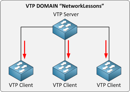
We have one VTP server. This is the switch where you create/modify or delete VLANs. The other switches are VTP clients. The VTP configuration has a revision number that increases every time you make a change. Every time you make a change on the VTP server, this will be synchronized to the VTP clients. Oh, and by the way, you can have multiple VTP servers since it also functions as a VTP client, so you can make changes on multiple switches in your network. To make VTP work, you need to set up a VTP domain name, which you can just make up as long as you configure it to be the same on all your switches.
This is the short version of what I just described:
- VTP adds / modifies / deletes VLANs.
- For every change, the revision number will increase.
- The latest advertisement will be sent to all VTP clients.
- VTP clients will synchronize themselves with the latest information.
Besides the VTP server and VTP client, there’s also a VTP transparent, which is a bit different. Let me show you an example:
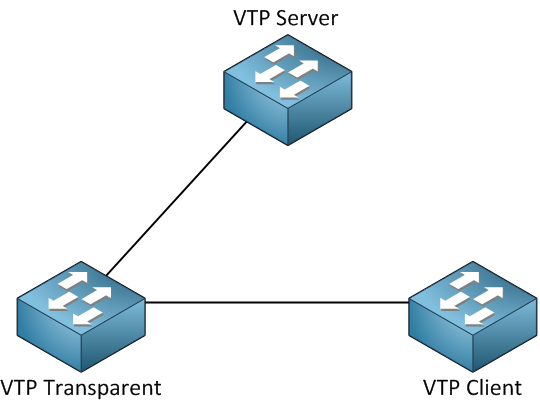
Our VTP Transparent will forward advertisements but will not synchronize itself. You can create VLANs locally, which is impossible on the VTP client. Let’s say you create VLAN 20 on our VTP server. This is what will happen:
- You create VLAN 20 on the VTP server.
- The revision number will increase.
- The VTP server will forward the latest advertisement to the VTP transparent switch.
- The VTP transparent will not synchronize itself but will forward the advertisement to the VTP client.
- The VTP client will synchronize itself with the latest information.
Here’s an overview of the 3 VTP modes:
| VTP Server | VTP Client | VTP Transparent | |
| Create/Modify/Delete VLANs | Yes | No | Only local |
| Synchronizes itself | Yes | Yes | No |
| Forwards advertisements | Yes | Yes | Yes |
Should you use VTP? It might sound useful, but VTP has a considerable security risk…the problem with VTP is that a VTP server is also a VTP Client, and any VTP client will synchronize itself with the highest revision number. The following situation can happen with VTP:
You have a network with a single VTP server and a couple of VTP client switches, and everything is working fine, but one day you want to test some stuff and decide to take one of the VTP clients out of the network and put it in a lab environment.
- You take the VTP client switch out of the network.
- You configure it, so it’s no longer a VTP Client but a VTP server.
- You play around with VTP, create some VLANs, and modify some.
- Every time you make a change, the revision number increases.
- You are done playing…you delete all VLANs.
- You configure the switch from VTP Server to VTP Client.
- You connect your switch to your production network.
What do you think the result will be? The revision number of VTP on the switch we played with is higher than the revision number on the switches of our production network. The VTP client will advertise its information to the other switches. They synchronize to the latest information, and POOF all your VLANs are gone! A VTP client can overwrite a VTP server if the revision number is higher because a VTP server is also a VTP client.
Yes, I know this sounds silly, but this is the way it works…very dangerous since you’ll lose all your VLAN information. Your interfaces won’t go back to VLAN 1 by default but will float around in no man’s land…
One more thing about VTP, let me give you another picture:
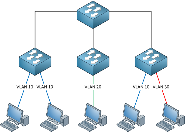
You see, we have computers in VLAN 10, 20 and 30. The links between the switches are trunks using the 802.1Q protocol and carrying all VLAN traffic. One of our computers in VLAN 10 sends a broadcast frame. Where do you think this broadcast frame will go?
Broadcast frames must be flooded by our switches, and since our trunks carry all VLANs, this broadcast will go everywhere. However, if you look at the switch in the middle, do you see any computer in VLAN 10? Nope, there’s only VLAN 20 there, which means this broadcast is wasted bandwidth. By enabling VTP pruning, we’ll ensure there is no unnecessary VLAN traffic on trunks when there’s nobody in a particular VLAN. Depending on your switch model, VTP pruning is either turned on or off by default.
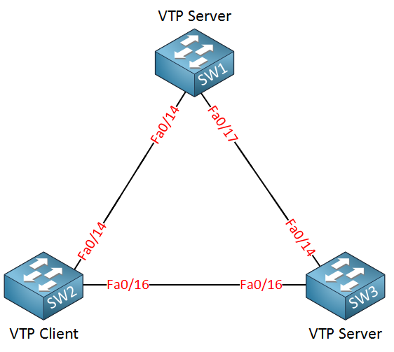
Let’s take a look at the configuration of VTP. I will be using three switches for this task. I erased the VLAN database and the startup configuration on all switches.
SW1#show vtp status
VTP Version                     : running VTP1 (VTP2 capable)
Configuration Revision          : 0
Maximum VLANs supported locally : 1005
Number of existing VLANs        : 5
VTP Operating Mode              : Server
VTP Domain Name                 :
VTP Pruning Mode                : Disabled
VTP V2 Mode                     : Disabled
VTP Traps Generation            : Disabled
MD5 digest                      : 0x57 0xCD 0x40 0x65 0x63 0x59 0x47 0xBD
Configuration last modified by 0.0.0.0 at 0-0-00 00:00:00
Local updater ID is 0.0.0.0 (no valid interface found)
SW2#show vtp status
VTP Version                     : running VTP1 (VTP2 capable)
Configuration Revision          : 0
Maximum VLANs supported locally : 1005
Number of existing VLANs        : 5
VTP Operating Mode              : Server
VTP Domain Name                 :
VTP Pruning Mode                : Disabled
VTP V2 Mode                     : Disabled
VTP Traps Generation            : Disabled
MD5 digest                      : 0x57 0xCD 0x40 0x65 0x63 0x59 0x47 0xBD
Configuration last modified by 0.0.0.0 at 0-0-00 00:00:00
Local updater ID is 0.0.0.0 (no valid interface found)
SW3#show vtp status
VTP Version                     : 2
Configuration Revision          : 0
Maximum VLANs supported locally : 1005
Number of existing VLANs        : 5
VTP Operating Mode              : Server
VTP Domain Name                 :
VTP Pruning Mode                : Disabled
VTP V2 Mode                     : Disabled
VTP Traps Generation            : Disabled
MD5 digest                      : 0x57 0xCD 0x40 0x65 0x63 0x59 0x47 0xBD
Configuration last modified by 0.0.0.0 at 0-0-00 00:00:00
Local updater ID is 0.0.0.0 (no valid interface found)
Depending on the switch model, you will see a similar output if you use the show vtp status command. There are a couple of interesting things to see here:
- Configuration revision 0: Each time we add or remove VLANs, this number will change. It’s 0 at the moment since I haven’t created or removed any VLANs.
- VTP Operating mode: the default is VTP server.
- VTP Pruning: this will help to prevent unnecessary traffic on your trunk links. More on this later.
- VTP V2 Mode: The switch can run VTP version 2, but it’s currently running VTP version 1.
SW1(config)#vlan 10
SW1(config-vlan)#name Printers
Let’s create a VLAN on SW1, and we’ll see if anything changes…
SW1#show vlan
VLAN Name                             Status    Ports
---- -------------------------------- --------- -------------------------------
1    default                          active    Fa0/1, Fa0/2, Fa0/3, Fa0/4
                                                Fa0/5, Fa0/6, Fa0/7, Fa0/8
                                                Fa0/9, Fa0/10, Fa0/11, Fa0/12
                                                Fa0/13, Fa0/14, Fa0/15, Fa0/22
                                                Fa0/23, Fa0/24, Gi0/1, Gi0/2
10   Printers                         active
My new VLAN shows up in the VLAN database. So far so good…
SW1#show vtp status
VTP Version                     : running VTP1 (VTP2 capable)
Configuration Revision          : 1
You can see that the configuration revision has increased by one.
SW2#show vtp status
VTP Version                     : running VTP1 (VTP2 capable)
Configuration Revision          : 0
SW3#show vtp status
VTP Version                     : 2
Configuration Revision          : 0
Unfortunately, nothing has changed on SW2 and SW3. This is because we need to configure a VTP domain name before it starts working.
SW2#debug sw-vlan vtp events
vtp events debugging is on
SW3#debug sw-vlan vtp events
vtp events debugging is on
Before changing the domain name, I’m going to enable a debug using the debug sw-vlan vtp events command. This way, we can see in real-time what is going on.
SW1(config)#vtp domain NETWORKLESSONS
Changing VTP domain name from NULL to NETWORKLESSONS
SW2#
VTP LOG RUNTIME: Summary packet received in NULL domain state
VTP LOG RUNTIME: Summary packet received, domain = NETWORKLESSONS, rev = 1, followers = 1, length 77, trunk Fa0/16
VTP LOG RUNTIME: Transitioning from NULL to NETWORKLESSONS domain
VTP LOG RUNTIME: Summary packet rev 1 greater than domain NETWORKLESSONS rev 0
You will see the following debug information on SW2 and SW3; there are two interesting things we can see here:
- The switch receives a VTP packet from domain “NETWORKLESSONS” and decides to change its own domain name from “NULL” (nothing) to “NETWORKLESSONS.” It will only change the domain name if it doesn’t have a domain name.
- The switch sees that the VTP packet has a higher revision number (1) than what it currently has (0), and as a result, it will synchronize itself.
SW2#no debug all
All possible debugging has been turned off
SW3#no debug all
All possible debugging has been turned off
Make sure to disable the debug output before you get flooded with information.
SW2#show vtp status
VTP Version                     : running VTP1 (VTP2 capable)
Configuration Revision          : 1
SW3#show vtp status
VTP Version                     : 2
Configuration Revision          : 1
The revision number on SW2 and SW3 is now “1”.
SW2#show vlan
VLAN Name                             Status    Ports
---- -------------------------------- --------- -------------------------------
1    default                          active    Fa0/1, Fa0/2, Fa0/3, Fa0/4
                                                Fa0/5, Fa0/6, Fa0/7, Fa0/8
                                                Fa0/9, Fa0/10, Fa0/11, Fa0/12
                                                Fa0/13, Fa0/14, Fa0/15,
                                                Fa0/23, Fa0/24, Gi0/1, Gi0/2
10   Printers                         active
SW3#show vlan
VLAN Name                             Status    Ports
---- -------------------------------- --------- -------------------------------
1    default                          active    Fa0/1, Fa0/2, Fa0/3, Fa0/4
                                                Fa0/5, Fa0/6, Fa0/7, Fa0/8
                                                Fa0/9, Fa0/10, Fa0/11, Fa0/12
                                                Fa0/20, Fa0/22, Fa0/23,
                                                Gi0/1, Gi0/2
10 Printers active
The show vlan command tells us that SW2 and SW3 have learned VLAN 10 through VTP.
Since all switches are in VTP Server mode, I can create VLANs on any switch, and they should all synchronize:
SW2(config)#vlan 20
SW2(config-vlan)#name Servers
SW3(config)#vlan 30
SW3(config-vlan)#name Management
Let’s create VLAN 20 on SW2 and VLAN 30 on SW3.
SW1#show vlan
VLAN Name                             Status    Ports
---- -------------------------------- --------- -------------------------------
10   Printers                         active
20   Servers                          active
30   Management                       active
SW2#show vlan
VLAN Name                             Status    Ports
---- -------------------------------- --------- -------------------------------
10   Printers                         active
20   Servers                          active
30   Management                       active
SW3#show vlan
VLAN Name                             Status    Ports
---- -------------------------------- --------- -------------------------------
10   Printers                         active
20   Servers                          active
30   Management                       active
As you can see, all switches know about the VLANs. What about the revision number? Did it change?
SW1#show vtp status
VTP Version                     : running VTP1 (VTP2 capable)
Configuration Revision          : 3
SW2#show vtp status
VTP Version                     : running VTP1 (VTP2 capable)
Configuration Revision          : 3
SW3#show vtp status
VTP Version                     : 2
Configuration Revision          : 3
Each time I create another VLAN, the revision number increases by one. Let’s change the VTP mode on SW2 to see what it does.
SW2(config)#vtp mode client
Setting device to VTP CLIENT mode.
SW2#show vtp status
VTP Version                     : running VTP1 (VTP2 capable)
Configuration Revision          : 3
Maximum VLANs supported locally : 1005
Number of existing VLANs        : 7
VTP Operating Mode              : Client
It’s now running in VTP Client mode.
Right now, SW1 and SW3 are in VTP Server mode. SW2 is running VTP Client mode. I have disconnected the link between SW1 and SW3, so there is no direct connection between them.
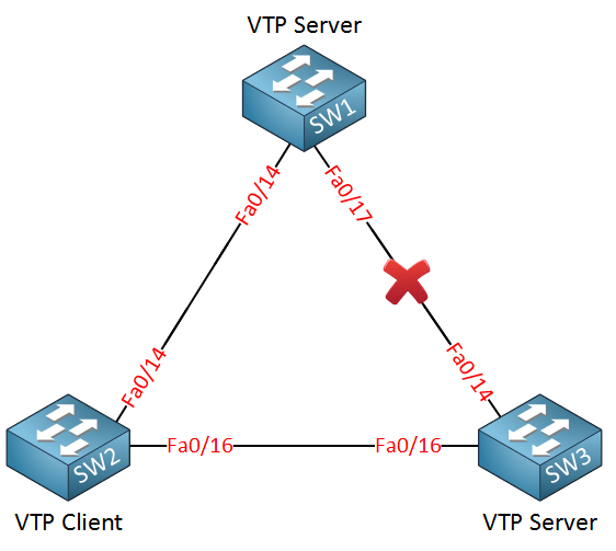
I’ll create another VLAN on SW1 so we can see if SW2 and SW3 will learn it.
SW1(config)#vlan 40
SW1(config-vlan)#name Engineering
I’ll call the new VLAN “Engineering.”
SW2#show vlan
VLAN Name                             Status    Ports
---- -------------------------------- --------- -------------------------------
10   Printers                         active
20   Servers                          active
30   Management                       active
40   Engineering                      active
SW2 learns about VLAN 40 through SW1.
SW3#show vlan
VLAN Name                             Status    Ports
---- -------------------------------- --------- -------------------------------
10   Printers                         active
20   Servers                          active
30   Management                       active
40   Engineering                      active
SW3 learns about VLAN 40 through SW2. SW2 as a VTP client, will synchronize itself and forward VTP advertisements.
SW2(config)#vlan 50
%VTP VLAN configuration not allowed when device is in CLIENT mode.
A switch running in VTP Client mode cannot create VLANs, so I get this error if I try to create one.
What about the VTP Transparent mode? That’s the last one we have to try…
I’ll change SW2 to VTP Transparent mode, and the link between SW1 and SW3 is still disconnected.
SW2(config)#vtp mode transparent
Setting device to VTP TRANSPARENT mode.
This is how we change SW2 to VTP Transparent mode.
SW1(config)#vlan 50
SW1(config-vlan)#name Research
Let’s create VLAN 50 for this experiment on SW1.
SW1#show vlan
VLAN Name                             Status    Ports
---- -------------------------------- --------- -------------------------------
10   Printers                         active
20   Servers                          active
30   Management                       active
40   Engineering                      active
50   Research                         active
It shows up on SW1 as expected.
SW2#show vlan
VLAN Name                             Status    Ports
---- -------------------------------- --------- -------------------------------
10   Printers                         active
20   Servers                          active
30   Management                       active
40   Engineering                      active
It doesn’t show up on SW2 because it’s in VTP transparent mode and doesn’t synchronize itself.
SW3#show vlan
VLAN Name                             Status    Ports
---- -------------------------------- --------- -------------------------------
10   Printers                         active
20   Servers                          active
30   Management                       active
40   Engineering                      active
50   Research                         active
It does show up on SW3! A switch in VTP Transparent mode will not synchronize itself, but it will forward VTP advertisements to other switches so they can synchronize themselves.
What will happen if I create a VLAN on SW2? Let’s find out!
SW2(config)#vlan 60
SW2(config-vlan)#name Cameras
SW2#show vlan
VLAN Name                             Status    Ports
---- -------------------------------- --------- -------------------------------
10   Printers                         active
20   Servers                          active
30   Management                       active
40   Engineering                      active
50   Research                         active
60   Cameras                          active
We can create this new VLAN on SW2 without any trouble. It’s in VTP Transparent mode, so we can do this.
SW1#show vlan
VLAN Name                             Status    Ports
---- -------------------------------- --------- -------------------------------
10   Printers                         active
20   Servers                          active
30   Management                       active
40   Engineering                      active
50   Research                         active
SW3#show vlan
VLAN Name                             Status    Ports
---- -------------------------------- --------- -------------------------------
10   Printers                         active
20   Servers                          active
30   Management                       active
40   Engineering                      active
50   Research                         active
VLAN 60 doesn’t show up on SW1 and SW3 because SW2 is in VTP Transparent mode. SW2 will not advertise its VLANs because they are only known locally.
Hi, thanks. This is good and useful lesson.
This topic clearifies different mode beautifully without any boredom
why we don’t use vtp in each network ?
can we use in big network?
You can use it but it has a security risk, a VTP client is able to overwrite the VTP server when its revision number is higher. It’s possible to wipe the VLAN Database on all your switches this way…
That is how one can do it once you have full understanding of the content.
Great job man.
Please help me with CCNA in this month.
Can you provide commands for the experiments please?