Lesson Contents
Spanning Tree Protocol (STP) is a network protocol that creates a loop-free network topology by blocking redundant links between switches. Redundant connections between switches are important because if you have only one link and that link fails, you’ll have reachability issues. The downside of redundant links is that they can introduce Layer 2 switching loops. Loops can cause broadcast storms, in which an Ethernet frame is forwarded from one switch to another, back to the first one, and so on. Your switches will be so busy forwarding these frames that eventually, they can take down the entire network. STP blocks redundant paths so that there is only one active path. When a link fails, a backup link can take over.
In this lesson, you will learn how STP works, and we’ll look at a basic configuration to see how it works on Cisco IOS switches.
Key Takeaways
- STP prevents network loops by blocking redundant ports while maintaining backup paths for redundancy
- Root bridge election is based on the lowest bridge ID (priority + MAC address)
- Three port roles exist:
- Root ports (shortest path to root)
- Designated ports (forwarding)
- Alternate/Blocked ports (loop prevention)
- Port states transition through Listening (15s) → Learning (15s) → Forwarding before transmitting data
- The default priority is 32768, so the MAC address becomes the tiebreaker for the root bridge. The priority can be modified.
- STP is enabled by default on Cisco switches and runs independently per VLAN (PVST)
Prerequisites
To follow this lesson, you should have a basic understanding of:
- Switches and switching
- VLANs and trunking
Why do we need Spanning Tree
What is a loop, and how do we get one? Let me show you an example:
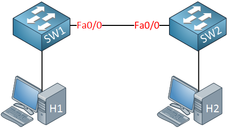
In the picture above, we have two switches. These switches are connected with a single cable, so there is a single point of failure. To get rid of this single point of failure, we will add another cable:
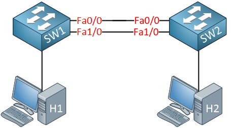
With the extra cable, we now have redundancy. Unfortunately for us, redundancy also brings loops. Why do we have a loop in the scenario above? Let me describe it to you:
- H1 sends an ARP request because it’s looking for the MAC address of H2. An ARP request is a broadcast frame.
- SW1 will forward this broadcast frame on all it interfaces, except the interface where it received the frame on.
- SW2 will receive both broadcast frames.
Now, what does SW2 do with those broadcast frames?
- It will forward it from every interface except the interface where it received the frame.
- This means that the frame that was received on interface Fa0/0 will be forwarded on Interface Fa1/0.
- The frame that was received on Interface Fa1/0 will be forwarded on Interface Fa0/0.
Do you see where this is going? We have a loop! Both switches will keep forwarding over and over again until the following happens:
- You fix the loop by disconnecting one of the cables.
- One of your switches will crash because they are overburdened with traffic.
Ethernet frames don’t have a TTL (Time to Live) value, so they will loop around forever. Besides ARP requests, many frames are broadcasted. For example, whenever the switch doesn’t know about a destination MAC address, it will be flooded.
How Spanning Tree solves loops
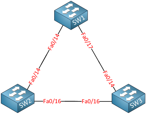
Spanning tree will help us to create a loop-free topology by blocking certain interfaces. Let’s take a look at how spanning tree work! Here’s an example:
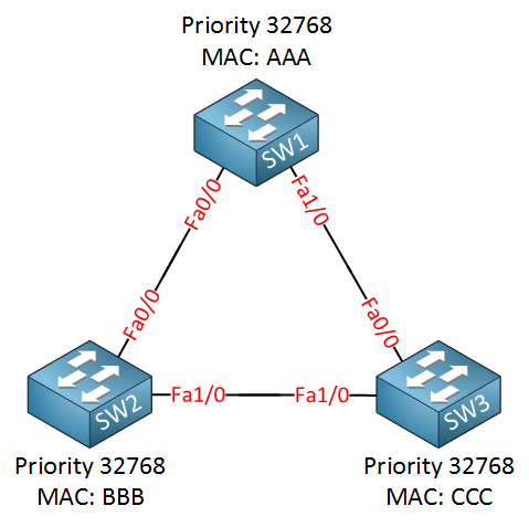
We have three switches, and as you can see, we have added redundancy by connecting the switches in a triangle, this also means we have a loop here. I have added the MAC addresses but simplified them for this example:
- SW1: MAC AAA
- SW2: MAC BBB
- SW3: MAC CCC
Since spanning tree is enabled, all our switches will send a special frame to each other called a BPDU (Bridge Protocol Data Unit). In this BPDU, there are two pieces of information that spanning tree requires:
- MAC address
- Priority
The MAC address and the priority together make up the bridge ID. The BPDU is sent between switches as shown in the following picture:
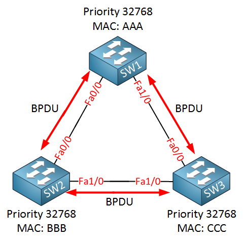
Spanning tree requires the bridge ID for its calculation. Let me explain how it works:
- First of all, spanning tree will elect a root bridge; this root bridge will be the one that has the best “bridge ID”.
- The switch with the lowest bridge ID is the best one.
- By default, the priority is 32768, but we can change this value if we want.
So who will become the root bridge? In our example, SW1 will become the root bridge! Priority and MAC address make up the bridge ID. Since the priority is the same on all switches, it will be the MAC address that is the tiebreaker. SW1 has the lowest MAC address thus the best bridge ID and will become the root bridge.
The ports on our root bridge are always designated, which means they are in a forwarding state. Take a look at the following picture:
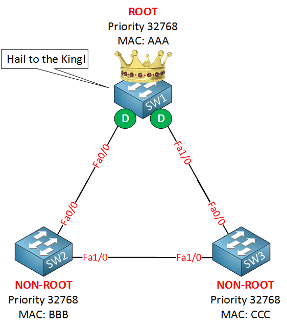
Above, you see that SW1 has been elected as the root bridge and the “D” on the interfaces stands for designated.
Now we have agreed on the root bridge, our next step for all our “non-root” bridges (so that’s every switch that is not the root) will have to find the shortest path to our root bridge! The shortest path to the root bridge is called the “root port”. Take a look at my example:
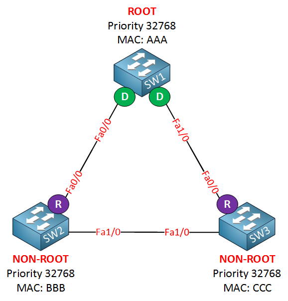
I’ve put an “R” for “root port” on SW2 and SW3. Their Fa0/0 interface is the shortest path to get to the root bridge. In my example, I’ve kept things simple, but “shortest path” in spanning tree means it will actually look at the speed of the interface. Each interface has a certain cost, and the path with the lowest cost will be used. Here’s an overview of the interfaces and their cost:
- 10 Mbit = Cost 100
- 100 Mbit = Cost 19
- 1000 Mbit = Cost 4
Excellent!…we have designated ports on our root bridge and root ports on our non-root bridges, we still have a loop, however, so we need to shut down a port between SW2 and SW3 to break that loop. So which port are we going to shut down? The one on SW2 or the one on SW3? We’ll look again at the best bridge ID:
- Bridge ID = Priority + MAC address.
Lower is better, both switches have the same priority, but the MAC address of SW2 is lower, which means that SW2 will “win this battle”. SW3 is our loser here which means it will have to block its port, effectively breaking our loop! Take a look at my example:
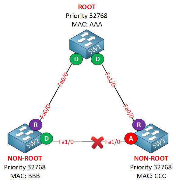
If you look at the link between SW2 and SW3, you can see that the Fa1/0 interface of SW3 says “A” which stands for alternate. An alternate port is blocked! Sometimes the alternate port is called the ND (Non Designated) port. By shutting down this interface, we have solved our loop problem.
Because the default priority is 32768, the MAC address is the tie-breaker for selecting the root bridge. What switch do you think will be elected as the root bridge in a production network?
Your brand spanking new switch or that dirty old switch that has been used as a dust collector for the last 8 years?
The old switch probably has a lower MAC address and thus will be elected as the root bridge. Doesn’t sound like a good idea, right? That’s why we can change the priority to determine what switch will become the root bridge.
Are you following me so far? Good! You just learned the basics of spanning tree. Let’s add some more detail to this story…
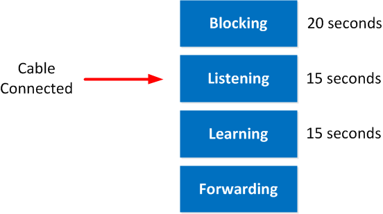
Let’s continue our spanning tree story and further enhance your knowledge. If you have played with some Cisco switches before, you might have noticed that every time you plugged in a cable, the led above the interface was orange and after a while became green. What is happening at this moment is that spanning tree is determining the state of the interface; this is what happens as soon as you plug in a cable:
- The port is in listening mode for 15 seconds. In this phase, it will receive and send BPDUs, still, neither learning MAC addresses nor data transmission.
- The port is in learning mode for 15 seconds. We are still sending and receiving BPDUs, but now the switch will also learn MAC addresses. Still no data transmission, though.
- Now we go in forwarding mode, and finally, we can start transmitting data!
Here’s a picture to visualize it:
Configuration
Now you have an idea what spanning tree is about. Let’s take a look at some Cisco switches to see how we can configure them. I will use the same topology that I showed you earlier, but we have different interfaces.
This is the topology we will use. Spanning tree is enabled by default; let’s start by checking some show commands.
SW1#show spanning-tree

VLAN0001
Spanning tree enabled protocol ieee
Root ID    Priority    32769
Address     000f.34ca.1000
Cost        19
Port        19 (FastEthernet0/17)
Hello Time   2 sec  Max Age 20 sec  Forward Delay 15 sec

Bridge ID  Priority    32769  (priority 32768 sys-id-ext 1)
Address     0011.bb0b.3600
Hello Time   2 sec  Max Age 20 sec  Forward Delay 15 sec
Aging Time 300

Interface           Role Sts Cost      Prio.Nbr Type
------------------- ---- --- --------- -------- --------------------------------
Fa0/14              Desg FWD 19        128.16   P2p
Fa0/17              Root FWD 19        128.19   P2p
The show spanning-tree command is the most important show command to remember. There’s quite some stuff here so I’m going to break it down for you!
VLAN0001
  Spanning tree enabled protocol ieee
We are looking at the spanning tree information for VLAN 1. Spanning tree has multiple versions and the default version on Cisco switches is PVST (Per VLAN spanning tree). This is the spanning tree for VLAN 1
Root ID      Priority    32769
             Address     000f.34ca.1000
             Cost        19
             Port        19 (FastEthernet0/17)
Here you see the information of the root bridge. You can see that it has a priority of 32769 and its MAC address is 000f.34ca.1000. From the perspective of SW1 it has a cost of 19 to reach the root bridge. The port that leads to the root bridge is called the root port and for SW1 this is fa0/17.
Bridge ID  Priority    32769  (priority 32768 sys-id-ext 1)
             Address     0011.bb0b.3600
This part shows us the information about the local switch, SW1 in our case. There’s something funny about the priority here….you can see it shows two things:
- Priority 32769
- Priority 32768 sys-id-ext 1
The sys-id-ext value that you see is the VLAN number. The priority is 32768, but spanning tree will add the VLAN number, so we end up with a priority value of 32769. Last but not least, we can see the MAC address of SW1, which is 0011.bb0b.3600.
Hello Time 2 sec Max Age 20 sec Forward Delay 15 sec
Here’s some information on the different times that spanning tree uses:
- Hello time: every 2 seconds, a BPDU is sent.
- Max Age: If we don’t receive BPDUs for 20 seconds, we know something has changed in the network, and we need to re-check the topology.
- Forward Delay: This timer is used for the listening and learning states. We remain in each state for the duration of the forward delay, which is 15 seconds by default.
Interface           Role Sts Cost      Prio.Nbr Type
------------------- ---- --- --------- -------- --------------------------------
Fa0/14              Desg FWD 19        128.16   P2p
Fa0/17              Root FWD 19        128.19   P2p
The last part of the show spanning tree commands show us the interfaces and their status. SW1 has two interfaces:
• Fa0/14 is a designated port and in (FWD) forwarding mode.
• Fa0/17 is a root port and in (FWD) forwarding mode.
The prio.nbr you see here is the port priority that I explained earlier. We’ll play with this in a bit.
Because only non-root switches have a root port I can conclude that SW1 is a non-root switch. I know that fa0/17 on SW1 leads to the root bridge.
Let’s take a look at SW2 to see what we find:
SW2#show spanning-tree

VLAN0001
  Spanning tree enabled protocol ieee
  Root ID    Priority    32769
             Address     000f.34ca.1000
             Cost        19
             Port        18 (FastEthernet0/16)
             Hello Time   2 sec  Max Age 20 sec  Forward Delay 15 sec

 Bridge ID  Priority    32769 (priority 32768 sys-id-ext 1)
             Address     0019.569d.5700
             Hello Time   2 sec  Max Age 20 sec  Forward Delay 15 sec
             Aging Time 300

Interface           Role Sts Cost      Prio.Nbr Type
------------------- ---- --- --------- -------- --------------------------------
Fa0/14              Altn BLK 19      128.16   P2p
Fa0/16              Root FWD 19      128.18   P2p
What do we see here?
Root ID    Priority    32769
             Address     000f.34ca.1000
             Cost        19
             Port        18 (FastEthernet0/16)
Here we see information about the root bridge. This information is similar to what we saw on SW1. The root port for SW2 seems to be fa0/16.
Bridge ID  Priority    32769  (priority 32768 sys-id-ext 1)
             Address     0019.569d.5700
This is the information about SW2. The priority is the same as on SW1. Only the MAC address (0019.569d.5700) is different.
Interface           Role Sts Cost      Prio.Nbr Type
------------------- ---- --- --------- -------- --------------------------------
Fa0/14              Altn BLK 19        128.16   P2p
Fa0/16              Root FWD 19        128.18   P2p
This part looks interesting; there are two things we see here:
• Interface fa0/14 is an alternate port and in (BLK) blocking mode.
• Interface fa0/16 is a root port and in (FWD) forwarding mode.
Last but not least, let’s check SW3:
SW3#show spanning-tree

VLAN0001
  Spanning tree enabled protocol ieee
  Root ID    Priority    32769
             Address     000f.34ca.1000
             This bridge is the root
             Hello Time   2 sec  Max Age 20 sec  Forward Delay 15 sec

  Bridge ID  Priority    32769  (priority 32768 sys-id-ext 1)
             Address     000f.34ca.1000
             Hello Time   2 sec  Max Age 20 sec  Forward Delay 15 sec
             Aging Time 300

Interface        Role Sts Cost      Prio.Nbr Type
---------------- ---- --- --------- -------- --------------------------------
Fa0/14           Desg FWD 19        128.14   P2p
Fa0/16           Desg FWD 19        128.16   P2p
Let’s break down what we have here:
Could you please post some details about RSTP and MSTP.
Thanks In Advance.
I will add those in the future, no problem.
Possibly the best and simplest explanation I have read, excellent work
Rene,
Thanks for explaining this. It’s very clear and informative.
I would like to ask you about what software or stencils (if you use Visio) you use for your diagrams? I really like them and I would like to use something like it for my own (personal) home network.
Looking at the picture quality, I’m going to assume it’s a Mac OS X based software! Can you please advise?
Thanks again mate.
Hi Karl, you are welcome. I’m using Microsoft Visio 2010 to draw the pictures and the excellent free stencils from http://www.visiocafe.com/vsdfx.htm.
Rene